
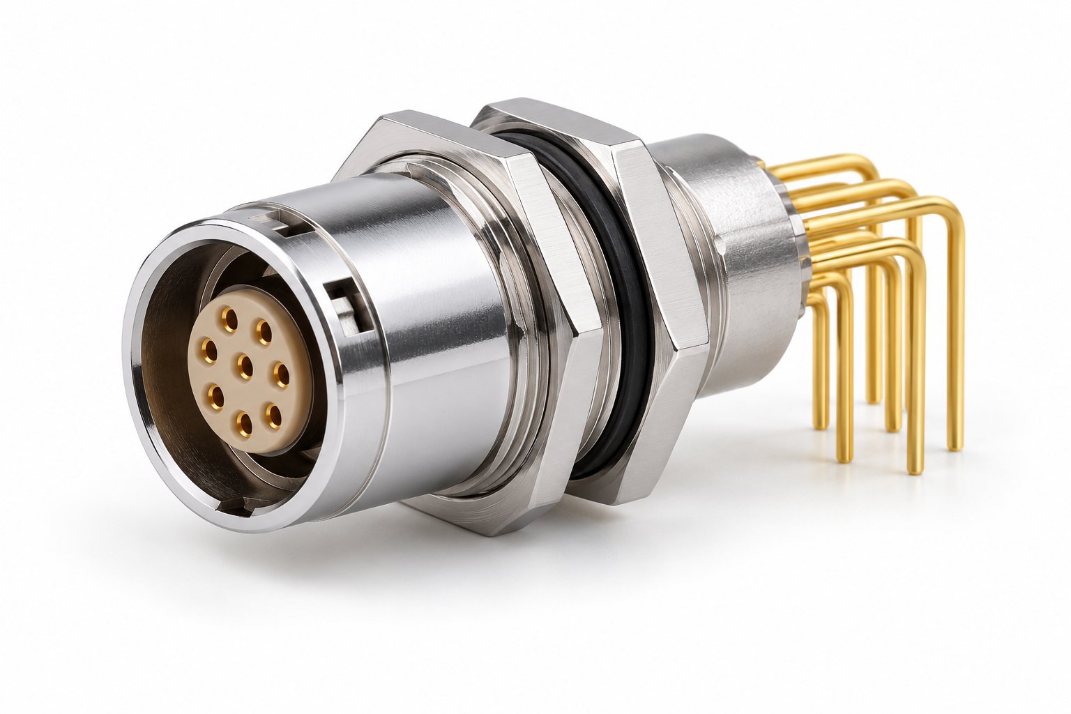
One push-pull series shares the same shell and latch. What changes is the back end. TRCONN push-pull lines come in 3 termination layouts. The choice follows where the wires go. A cable, a parallel board, or a perpendicular board.
Solder-wire terminations
Solder contacts fit cable assemblies. The harness shop solders each conductor to its contact inside the insulator. Then the collet or sleeve clamps the cable. This layout is for plugs and cable-side sockets. For example the B Series TGG straight plug or the ZGG fixed socket in its wire version. Cable OD on finished assemblies is 2.5–8.2 mm. D-type clamps step 3.2 to 7.2 mm.
Straight-pin PCB terminations
Straight pins exit axially from the back of the insulator. So the connector solders directly onto a PCB. That board plane is perpendicular to the mating axis. Compact devices put the board flat behind the front panel. They use this layout. The B Series ZPG is the board-level socket. The ZXG adds double-nut panel fixing to the same idea. Pin grids are 5.08 mm on the 00B size. 7.62 mm on 0B and 1B.
Elbow-pin PCB terminations
When the board lies parallel to the panel, straight pins cannot reach it. Elbow-pin variants bend the solder tail through 90°. The connection plane drops to board level. No standoffs needed. The B Series ZCG long elbow-pin socket is the standard example. Same shell, thread and double-nut fixing as the straight-pin ZCG. Different tail geometry.
Decision summary
| Your assembly | Termination | Example |
|---|---|---|
| Cable harness, soldered by hand or bench | Solder-wire | TGG plug, ZGG/ZEG/ZCG sockets |
| PCB perpendicular to the mating axis | Straight-pin PCB | ZPG, ZXG sockets |
| PCB parallel to the panel | Long elbow-pin PCB | ZCG long elbow-pin socket |
Two ordering details worth checking
- Termination affects the length code. PCB and solder-wire versions of the same shell have different L and N dimensions in the catalogue. So check the rear clearance in your housing against the right table.
- Keying stays independent of termination. The positioning-pin letter (G standard, plus 30°/60°/90°/45°/155° options) is chosen separately. So you can mix terminations on one panel. Mismating still prevented.
Send us the board orientation, contact count and cable spec. We will return the termination layout and part code that fits.
Choose a termination