
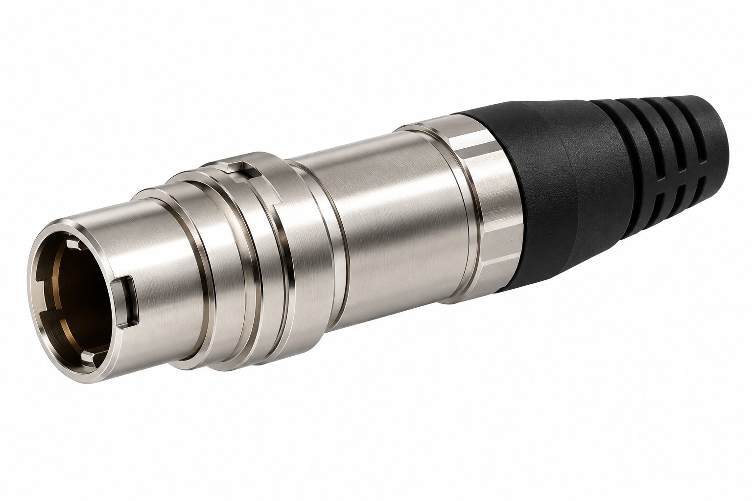
The cable end is the half of a push-pull connector that decides whether your harness survives assembly, routing and field conditions. This guide walks through tail style, cable clamp selection, exit direction, strain relief and sealing expectations — for the cable side only.
- The cable end comprises the backshell body, cable clamp, tail style (nut or molded sleeve), exit direction and any cable-side sealing features.
- Nut tails suit field assembly and repair; molded sleeves suit fixed, high-volume harnesses with defined cable OD.
- D-type clamps are coded by cable OD: D32, D42, D52, D62, D72 for 3.2, 4.2, 5.2, 6.2 and 7.2 mm respectively.
- IP50 mated protection is not cable-side waterproofing. For water ingress, specify an IP68 series connector such as the F Series.
- Strain relief depends on correct clamp sizing, cable jacket compatibility and proper bend allowance — confirm exact bend limits with the supplier for your build.
What this guide covers
- What the cable end includes on a push-pull plug
- Nut tail vs molded sleeve tail
- Selecting the cable clamp by cable OD (D-type codes)
- Exit direction: straight vs 90-degree elbow
- Strain relief and bending practice
- What the cable end seals — and what it does not
- Inquiry checklist for push pull cable ends and end fittings
- FAQ
1. What the cable end includes on a push-pull plug
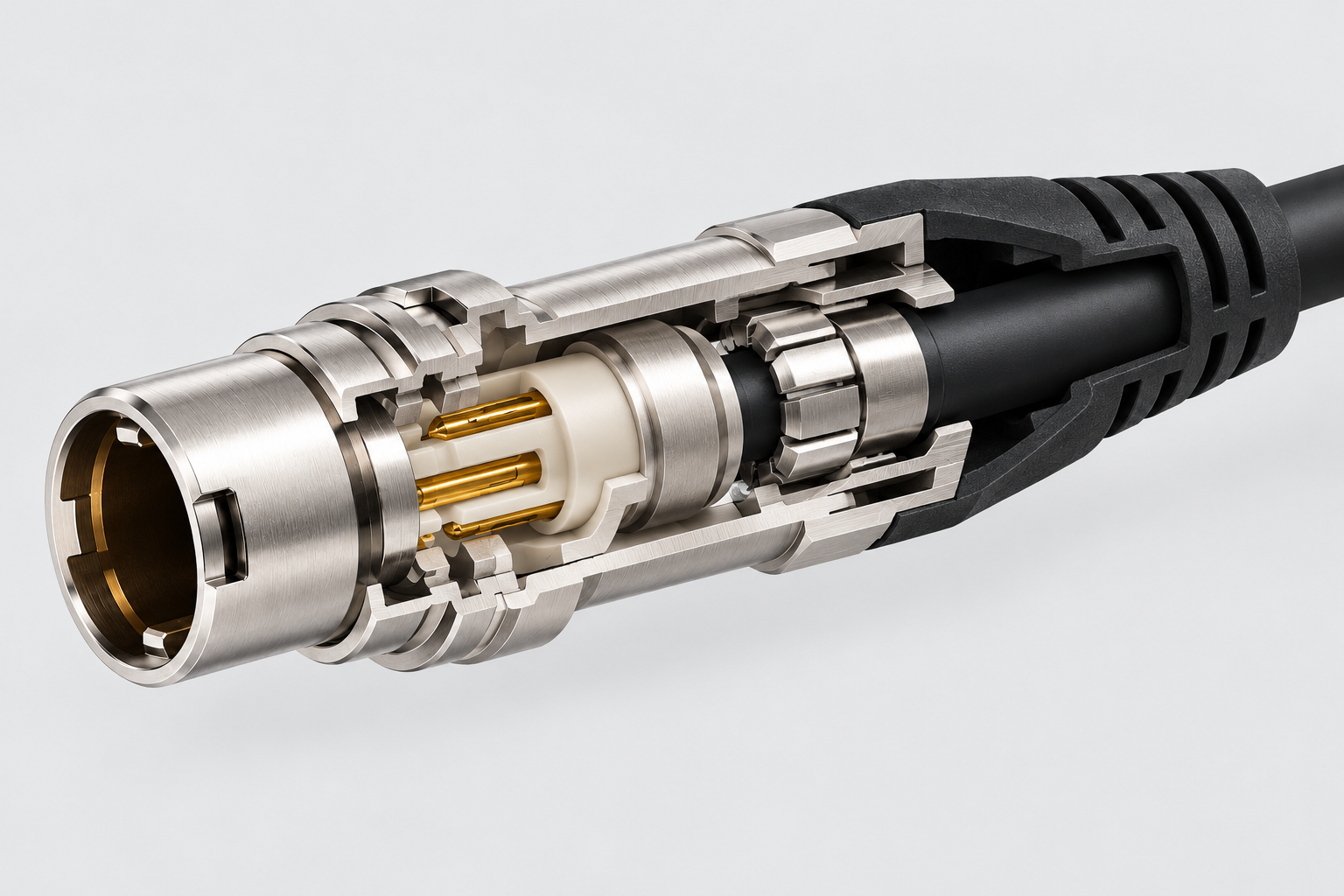
The cable end of a push-pull connector is everything behind the latch mechanism. On a typical plug, the cable-side assembly consists of:
- Backshell / tail body — the housing that threads onto or integrates with the connector shell and guides the cable away.
- Cable clamp — the mechanical element that grips the cable jacket or strength members to provide strain relief.
- Tail style — either an exposed nut or a molded protective sleeve that covers the clamp and cable exit.
- Exit direction — straight (in line with the connector axis) or 90-degree elbow.
- Sealing features — O-rings or gaskets intended for the mating face or panel, not necessarily for the cable jacket.
These parts work together. A clamp sized for 5.2 mm cable on a 6.2 mm jacket will not grip, and a molded sleeve designed for one OD range will not stretch to another. The decisions below are therefore interdependent — start with the cable, then work outward.
2. Nut tail vs molded sleeve tail: where each fits
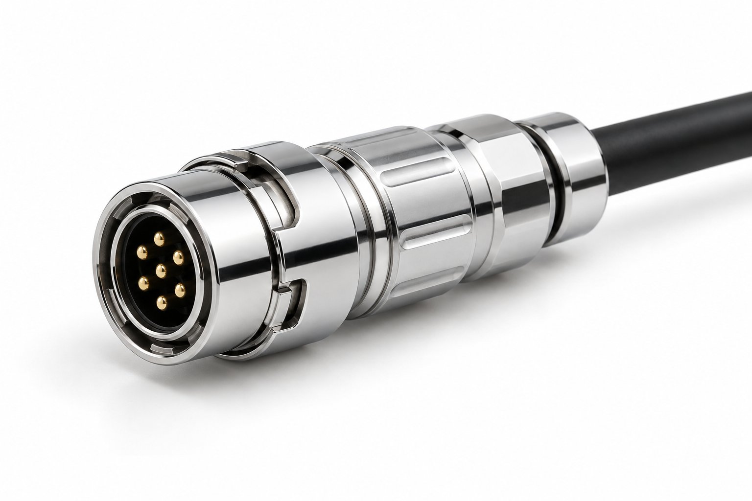
Two tail styles dominate the cable end of push-pull connectors. Choosing between them is primarily a question of assembly method, cable OD definition and serviceability.
Nut tail
A nut tail uses a threaded backnut to compress the cable clamp. The cable exit and clamp are visible and accessible. This style suits:
- Field assembly or repair where the harness may need re-termination.
- Prototyping and low-volume builds where cable OD varies between units.
- Harnesses that will be inspected or reworked after initial assembly.
Examples include the B Series TGG Push-Pull Straight Plug, which offers solder, crimp and PCB terminations and accepts shell sizes 0B/1B/2B with IP50 mated protection.
Molded sleeve tail
A molded sleeve encases the clamp and cable exit in a protective boot. It provides a defined cable exit profile and protects the clamp from contamination and handling damage. It suits:
- High-volume production harnesses where cable OD is fixed and repeatable.
- Installations where the cable exit is exposed to abrasion or incidental contact.
- Applications requiring a clean, sealed-looking transition from connector to cable.
The B Series TGG Sleeve Version is a representative example. It uses D-type cable clamp codes D32/D42/D52/D62/D72 for 3.2/4.2/5.2/6.2/7.2 mm cable OD, covers shell sizes 00B–4B, and carries IP50 mated protection, >5,000 mating cycles, and an operating range of −55 to +250 °C.
Two points to keep straight when comparing these models: shell sizes are model-specific — 0B/1B/2B for the standard TGG straight plug versus 00B–4B for the sleeve version and the THG elbow — and the 2–32 contact range is the series total, so the maximum contact count for a given shell size must be confirmed with the supplier.
Comparison table
| Consideration | Nut tail | Molded sleeve tail |
|---|---|---|
| Assembly | Field-serviceable; clamp accessible | Typically factory-assembled or requires controlled rework |
| Cable OD flexibility | Accepts a range within clamp limits | Matched to a specific D-code OD |
| Protection at exit | Exposed clamp; relies on cable jacket | Sleeve shields clamp and exit from abrasion |
| Best fit | Prototyping, MRO, low volume | Series production, defined harness |
| Example product | B Series TGG straight plug | B Series TGG sleeve version |
3. Selecting the cable clamp by cable OD (D-type codes)
The cable clamp is the single most important cable-end decision for strain relief. It must grip the cable jacket without crushing conductors or slipping under load.
TRCONN uses D-type clamp codes that map directly to nominal cable outside diameter:
| Clamp code | Nominal cable OD (mm) | Typical cable examples (for reference only) |
|---|---|---|
| D32 | 3.2 | Small signal / sensor cables |
| D42 | 4.2 | Light control and instrumentation cables |
| D52 | 5.2 | Standard multi-core industrial cables |
| D62 | 6.2 | Power + signal composite cables |
| D72 | 7.2 | Larger jacketed cables |
These sizes appear on the B Series TGG Sleeve Version and are representative of the B Series range. Other shell sizes and clamp variants exist; confirm availability for your exact shell size and cable.
How to specify the clamp
- Measure the cable jacket OD at the point where the clamp will sit, not at the cable end. Jacket diameter can vary along a cable run.
- Check tolerance — cable OD is rarely exactly 5.2 mm. Provide the measured range (e.g., 5.1–5.3 mm) to the supplier.
- Match to the nearest D-code. If the cable falls between two codes, the clamp may not grip adequately; the supplier can advise on an alternative clamp or cable build.
- Confirm jacket material compatibility — clamp designs differ in how they compress the jacket. Soft jackets may require a different clamp style than hard jackets. Ask the supplier for guidance on your specific jacket.
The OD values above are nominal reference points; the actual clamping range each code accepts should be confirmed with the supplier before fixing the design. Do not assume a clamp will hold a cable outside its nominal OD without confirmation. A clamp that is too large will allow the cable to pull out; one that is too small may damage conductors.
4. Exit direction: straight vs 90-degree elbow
The exit direction determines how the cable leaves the connector and how much space the harness consumes behind the panel.
Straight exit
A straight plug continues the connector axis. It is the default choice when there is clear space behind the connector and the cable can be routed without an immediate bend. Straight plugs are common in rack-mounted instrumentation and panel-mount designs where cable dressing is planned.
The B Series TGG straight plug is a straight-exit example with 2–32 pins, >5,000 mating cycles, and a brass chrome-plated shell.
90-degree elbow
A 90-degree elbow turns the cable exit parallel to the panel or enclosure surface. This is useful when:
- Depth behind the connector is limited (e.g., shallow enclosures).
- The cable must run along a surface immediately after the connector.
- Bend radius at the exit would otherwise be too tight for a straight plug.
The B Series THG 90-degree elbow plug offers both nut-tail and sleeve-tail versions, shell sizes 00B–4B, 2–32 contacts, and the same latch and keying as straight plugs. It uses solder termination and carries IP50 mated protection.
Note that an elbow changes the cable path but does not by itself increase the minimum bend radius of the cable. The cable’s own bend limit still applies after the elbow.
5. Strain relief and bending practice at the cable exit
Strain relief protects the termination from mechanical loads. The cable end contributes to strain relief through the clamp, the tail style and the cable path.
What the clamp does
The clamp transfers axial pull and torsional load from the cable jacket to the connector backshell, rather than to the solder joints or crimp contacts. A correctly sized clamp on a compatible jacket will limit cable movement at the termination.
Bending at the exit
The cable should exit the connector with a gentle bend, not a sharp kink. Sharp bends concentrate stress on the jacket and conductors, and can lead to premature failure. As a working method, treat the cable manufacturer’s stated minimum bend radius as the routing constraint, then confirm the strain-relief performance of the chosen clamp and tail combination with the connector supplier for your build. As a practical rule:
- Route the cable so that the bend starts at least a short distance behind the connector, not immediately at the clamp.
- Use a 90-degree elbow if the routing requires an immediate turn.
- Provide support (clips, ties or conduit) to keep the cable from hanging on the connector.
Do not use the connector itself as a cable support. The clamp is designed for strain relief, not for suspending cable weight.
Molded sleeve and strain relief
A molded sleeve can improve strain relief by distributing bending forces over a longer transition. However, the sleeve is not a substitute for correct clamp sizing. The clamp must still match the cable OD.
6. What the cable end does and does not seal
Sealing is often misunderstood on push-pull connectors with a defined IP rating. The IP rating applies to the mated connector pair, not to the cable entry.
IP50 mated
The B Series TGG and THG plugs listed here carry IP50 mated protection. This means they are protected against dust ingress (not dust-tight) when mated. IP50 does not imply water resistance.
The cable end — the tail, clamp and cable exit — is not sealed to the same degree unless the connector is specifically designed for it. Moisture can enter along the cable jacket or through the clamp area if the cable end is exposed to water.
Front seal vs cable-side sealing
Some plugs include a front O-ring that seals the mating face against a panel surface. This is a panel seal, not a cable-end seal. The B Series TEG front-sealed plug uses an O-ring at the mating face to seal the panel surface against dust. It has a sleeve tail with cable clamp but does not add cable-side waterproofing.
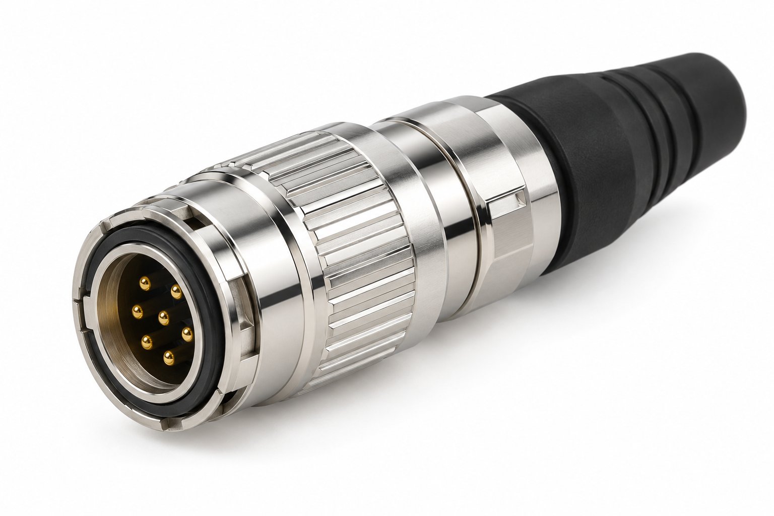
If the application requires water resistance at the cable end, specify an IP68 connector series. The F Series TGG High-Sealing Long Straight Plug offers IP68 protection with 2–27 pins, >5,000 mating cycles, and long/short straight and 90-degree elbow exits. It uses a ring guiding groove and is designed for harsh environments where water ingress is a concern.
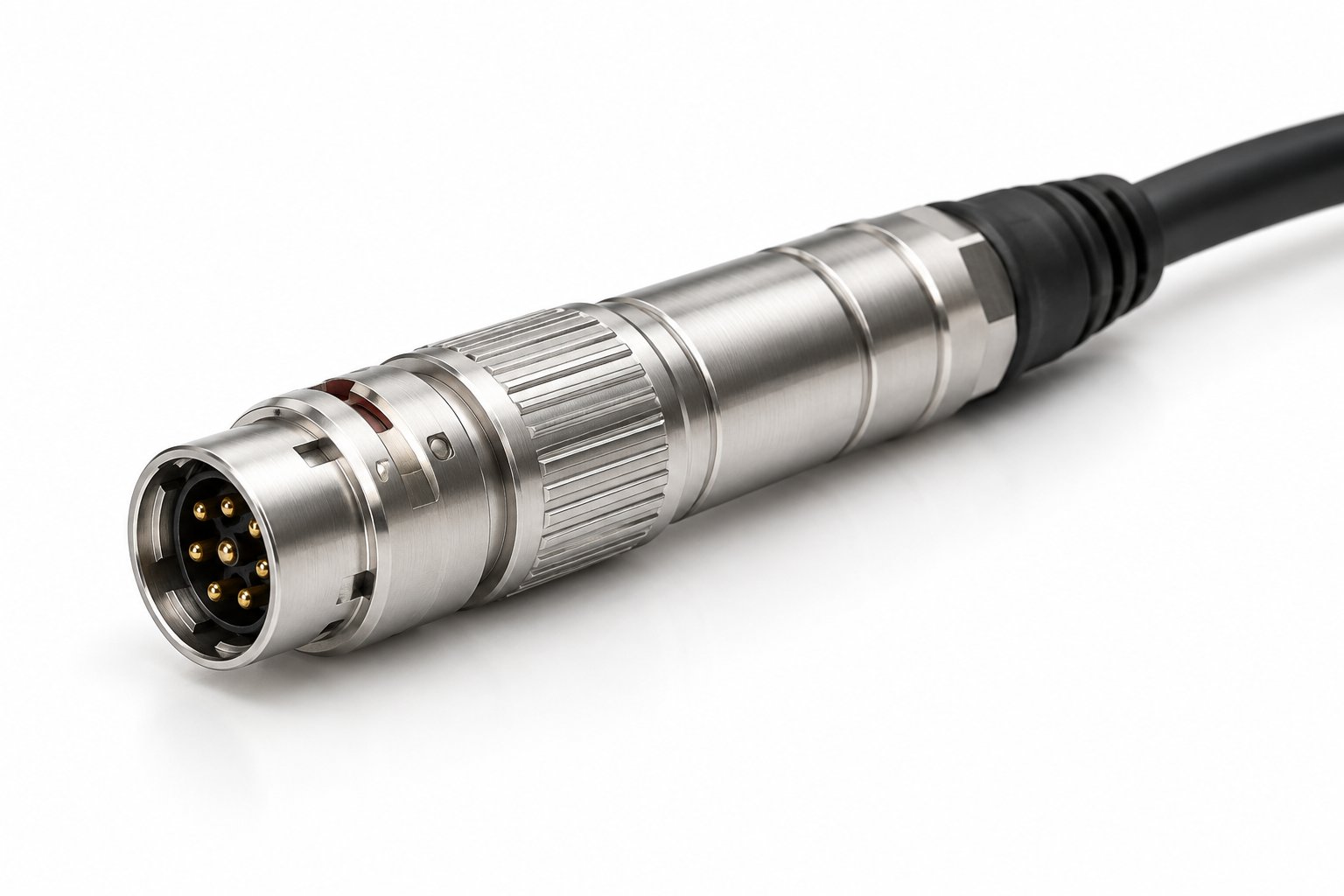
Sealing summary table
| Connector series / feature | Mated IP rating | Cable-end sealing | Typical application |
|---|---|---|---|
| B Series TGG (standard) | IP50 | Not water-resistant at cable entry | Indoor industrial, instrumentation |
| B Series TEG (front seal) | IP50 | Panel face sealed; cable entry not water-resistant | Dusty panel-mount, indoor |
| F Series TGG (IP68) | IP68 | Sealed design for water exposure | Outdoor, washdown, marine |
Always confirm the exact IP rating and sealing conditions for your specific connector and cable build. The IP rating describes the mated connector under defined test conditions; the depth and duration behind a rating such as IP68, and the sealing actually achieved at your cable end, depend on the specific harness and must be confirmed with the supplier. IP ratings are not a substitute for proper cable routing and protection.
7. Inquiry checklist for push pull cable ends and end fittings
When requesting a quote or technical confirmation for the cable end of a push-pull connector, provide the following information. This reduces back-and-forth and ensures the supplier can match the tail style and clamp to your harness.
| Item | What to provide | Why it matters |
|---|---|---|
| Cable OD | Measured jacket diameter (mm) and tolerance | Determines D-code clamp selection |
| Tail style | Nut tail or molded sleeve | Assembly method and serviceability |
| Exit direction | Straight or 90-degree elbow | Routing and space behind panel |
| Shell size | Series and model with its size range — e.g., 0B/1B/2B for the standard TGG straight plug; 00B–4B for the sleeve version and THG elbow | Compatibility with contact count and housing |
| Contact count | Number of pins required (the 2–32 / 2–27 figures are series totals; confirm the maximum for your shell size) | Connector family selection |
| Termination type | Solder, crimp or PCB | Backshell and clamp compatibility |
| Sealing requirement | IP50 or IP68; indoor vs outdoor | Series selection (B vs F) |
| Environment | Temperature, humidity, vibration, chemicals | Material and sealing suitability |
| Strain relief needs | Pull force, bending, cable weight | Clamp and sleeve design confirmation |
| Quantity | Prototype, pilot or production volume | Packaging and lead time |
Include a drawing or photo of the cable cross-section if available. If the cable is custom or unfamiliar, the supplier may ask for a sample to confirm clamp fit.
FAQ
- Can I use a nut tail and a sleeve tail interchangeably on the same connector?
- Tail style is typically determined by the connector model. Some series offer both options, but the backshell and clamp may differ. Confirm with the supplier which tail styles are available for your chosen connector.
- What happens if my cable OD is between two D-codes?
- The clamp may not provide adequate strain relief. Provide the exact measured OD and tolerance to the supplier; they may recommend an alternative clamp or a different cable jacket thickness.
- Does IP50 mean the cable end is waterproof?
- No. IP50 is a mated dust-protection rating. It does not indicate water resistance at the cable entry. For water exposure, specify an IP68 series connector such as the F Series.
- Can I get a 90-degree elbow with a molded sleeve?
- Yes, the B Series THG 90-degree elbow plug is available in both nut-tail and sleeve-tail versions. Confirm the specific shell size and cable OD with the supplier.
- What is the minimum bend radius for the cable at the exit?
- Bend radius depends on the cable construction and is not defined by the connector alone. Confirm the cable manufacturer’s recommendation and ensure the routing does not force a tight bend at the clamp.
Need help specifying the cable end?
Send your cable OD, clamp code preference and tail style requirement to our engineering team. We will confirm compatibility and suggest the right push pull cable ends and end fittings for your harness.
Contact us