
Termination Technology Guide
For low-to-medium volume builds with mixed wire gauges, a solder cup termination is often the most direct way to land a discrete wire on a circular push-pull connector, and for many harness shops it is the fastest option already on the bench. It is also the termination most sensitive to workmanship. This guide covers what the solder cup actually is, when it earns its place against crimp and PCB contacts, how to write a specification the supplier can quote against, and how to solder and inspect the joint so the connector is not the weak link on the assembly.
Key takeaways
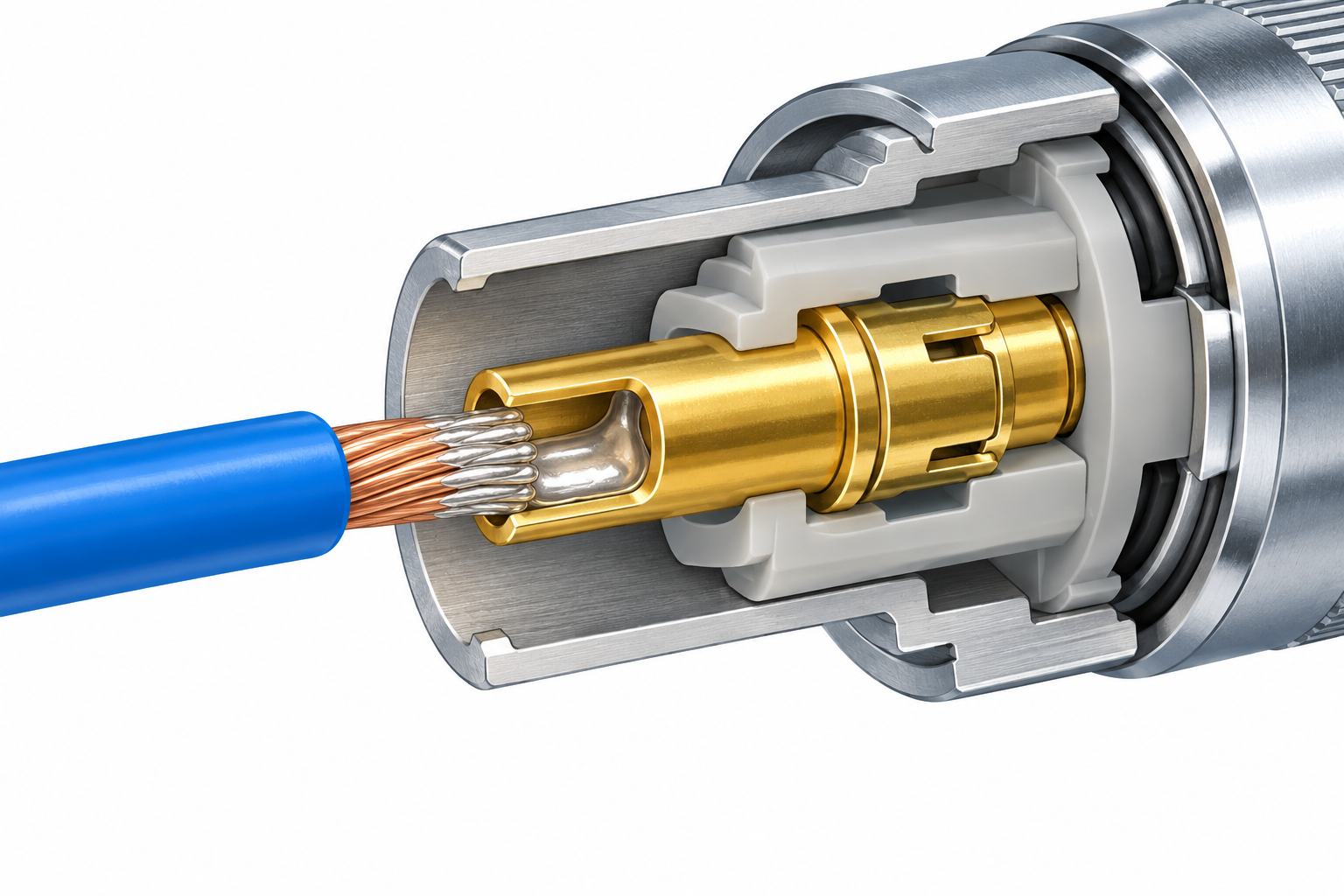
- A solder cup is a blind, cup-shaped contact tail. The stripped conductor sits in the cup and is soldered in place; there is no separate crimp contact, insertion tool or extraction tool in the chain.
- Solder cups suit low-to-medium volume harness builds, mixed wire sizes in one connector, and small shell sizes where a crimp contact system has little room.
- Crimp is the better answer when the build is repeatable at higher volume or when the harness is assembled away from the connector. PCB pins are the better answer when the connector lands directly on a board.
- Common solder cup field failures are workmanship-related: solder wicking up the stranded wire, melted insulation from an over-long dwell, or a cold joint from a dirty cup. Visual checks catch much of this, but some defects, such as a disturbed joint, also need a light mechanical check before the harness leaves the bench.
- The inquiry needs six items: pin count, termination style, cable diameter, exit direction, keying position and quantity. Anything less and the supplier is quoting a guess.
In this article
What a solder cup termination is
Inside a circular connector, every contact has two ends. One end is the mating side, shaped to engage the opposite half. The other end is the termination side, where the wire from the cable is attached. On a solder cup connector, that termination side is formed as a short cup with an open mouth facing the rear of the connector. You strip the wire, tin it if your process calls for tinning, insert it into the cup, apply heat and solder until the joint wets, then let it cool.
Two details separate the solder cup from other solder-based terminations. First, the cup is blind: solder and wire stop at the bottom of the cup, which limits how far the conductor can travel into the contact body. Second, the cup is sized to the conductor, not to a terminal barrel, so the wire gauges a given connector accepts are a function of the cup bore and the rear insert or grommet that seals and strain-relieves the cable.
Solder cups appear on plugs and on receptacles. On a plug, the cups are usually behind a rear shell or boot that the harness shop closes after soldering. On a fixed socket, the cups sit on the rear face of the connector so wires can be dressed away from the panel. That rear face is where most of the soldering access and most of the inspection access comes from, which is one reason panel-mounted sockets and solder cups are a common pairing.
The electrical job the joint has to do is modest. The cup is a mechanical and electrical splice between the conductor and a plated contact body. Where modern product data quantifies the connection, it usually does so at the contact pair level rather than the solder joint. The TRCONN B Series ZEG outer fixed socket, for example, publishes contact resistance ≤ 10 mΩ and insulation resistance ≥ 5,000 MΩ for the connector. A solder joint that wets properly contributes a small fraction of that contact resistance; a joint that does not, contributes a failure that no downstream test always catches. That asymmetry is the reason inspection matters more here than on a crimp line, where the tool either certifies the crimp or it does not.
Solder cup vs crimp vs PCB contacts
Buyers often ask which termination type is "better." There is no universal answer, only a fit between the termination and the build. The three types differ in where the labor happens, what tooling has to exist, and how easily the result can be reworked.
Solder cup
The labor is concentrated at the connector. One technician with a temperature-controlled iron and a fume extractor can terminate a connector. There is no crimp tool to calibrate, no contact to insert or extract, and no pull-test fixture that only works on one contact family. Changing wire gauge mid-build is trivial: a different cup accepts a different conductor. The trade is that the joint quality depends on the operator, and the joint is permanent. Rework is possible but requires desoldering the joint, which risks insulation damage a second time.
Crimp contacts
The labor is split. Contacts are crimped onto wires at a bench or with a semi-automatic press, then inserted into the connector body and locked. The crimp itself is highly repeatable when the tool and the contact are a matched pair and the operator follows the wire range. The cost is hidden in tooling and in documentation: the crimp tool, the insertion and extraction tools, and the pull-test values all belong to a specific contact family. Mixing wire sizes in one connector is constrained by the contact's wire range. At higher volumes the repeatability usually wins; at low volumes the tooling cost can dominate.
PCB pins
The connector is designed to sit on a board, with tails that drop into plated through-holes or land on pads. The termination happens during board assembly, so it inherits the board house's process control. There is no discrete wire and no hand operation on the harness. The limitation is architectural: a PCB-pin connector belongs at a board edge, not on the end of a flexible cable run. If the mechanical layout calls for a cable coming off a panel, PCB pins are the wrong answer regardless of how good the solder process is.
| Consideration | Solder cup | Crimp | PCB pin |
|---|---|---|---|
| Where the work happens | At the connector, by hand | At a bench or press, then inserted | At board assembly |
| Tooling needed | Iron, solder, fume extraction | Crimp tool, insertion and extraction tools, pull tester | Board assembly process |
| Wire gauge flexibility in one connector | High, within cup bore and insert limits | Limited by each contact's wire range | Not applicable |
| Rework | Possible, but risks insulation a second time | Contact can be extracted and replaced | Desoldering from the board |
| Best fit | Low-to-medium volume, mixed gauges, small shells, field repair | Repeatable volume builds | Board-mounted interfaces |
| Main quality risk | Operator-dependent joint | Wrong tool or wrong wire range | Board-level solder defects |
One practical point for specifiers: the same shell can often be offered with more than one termination style, which means the termination decision can be made late, after the mechanical layout is fixed. The TRCONN B Series TGG push-pull straight plug, for instance, is available with solder, crimp or PCB terminations across 2–32 pins, so the shell size and keying do not have to be re-engineered when the termination changes. That flexibility is worth knowing about before the drawing is frozen.
Writing the specification
A solder cup inquiry that only says "2B, 12 pin, solder" will come back with questions. The specification has to pin down the wire, the shell, the keying and the mounting, because each of those interacts with the others.
Wire gauge and insulation fit
The cup bore sets the largest conductor the contact will take comfortably. The rear insert or grommet sets the outer diameter range of the cable jacket or of the individual wires, and that is usually the tighter constraint. A connector that accepts the conductor may still not accept the insulation. When specifying, give the supplier the conductor size and the insulation outside diameter for each wire, or the overall cable diameter if a jacketed cable is used. Where a specific gauge matters to the design, treat it as a check-item with the supplier rather than assuming a cup size maps to a gauge. Ask what conductor range and what insulation diameter range the rear insert accepts for the pin count you have chosen.
Shell size and pin count
Shell size and pin count move together, but not in a simple ratio, because contact density depends on the contact size the shell was designed around. Product families usually publish the range. The TRCONN B Series ZEG outer fixed socket covers shell sizes 00B, 0B, 1B, 2B, 3B and 4B with 2–32 contacts; the B Series TGG plug and B Series ZGG fixed socket cover 0B, 1B and 2B with 2–32 pins. The F Series ZLG sealed socket covers 0F (102F) and 1F (103F) shells with 2–12 contacts. If your pin count sits near the top of a range, confirm the solder cup size and the wire gauge it will actually accept at that count before committing.
Keying
Push-pull connectors with multiple contacts need keying so the plug cannot be mated in the wrong orientation. In a multi-position scheme, one position is standard and the others are offset. On the B Series ZEG socket, the keying options are 0° (G, the standard position) plus A, B, C, J and F at 30°, 60°, 90°, 45° and 155° respectively. The TGG plug offers multi-position keying with the G-type standard key. If your design has more than one connector of the same shell size on the same panel, keying is not optional; it is the only thing preventing a cross-mate during service.
Panel fixing
How the receptacle attaches to the panel changes the mechanical drawing and the assembly sequence. The B Series ZEG outer fixed socket uses an external mounting thread with a lock washer through a plain clearance hole, so the panel needs a clearance hole rather than a threaded one. The B Series ZGG fixed socket uses an internal nut behind the panel, which keeps the front face clean. The F Series ZLG outer sealed socket uses an external thread with a front O-ring sealing against the housing wall. Pick the fixing that matches your panel machining and your sealing requirement, and state it explicitly in the inquiry, because it changes the part number.
Exit direction
Straight and 90° exits are both available on the TGG plug. Exit direction affects cable dressing, bend radius and whether the connector can sit close to a wall. It is also one of the items most often omitted from an inquiry, and one of the items that changes the part.
Soldering workmanship
The soldering itself is a hand process, so the control has to come from method and inspection rather than from a machine setting. A few principles cover most of the risk.
Heat control
Use a temperature-controlled iron with a tip sized to the cup, and keep the tip clean and tinned. The cup and the conductor should reach soldering temperature quickly and the joint should wet and finish. If the joint takes a long time to wet, the cause is usually a dirty or underpowered tip or an oxidized cup, not insufficient temperature. Raising the setpoint to force a faster joint drives heat into the insulator, which is the failure mode you are trying to avoid. The right iron temperature and dwell for your specific contact and wire are process parameters your soldering standard should define; do not carry a number across from a different connector family.
Keep solder out of the wicking zone
Solder wicking up a stranded conductor beyond the cup is a defect. It turns the flexible strand into a rigid stub, and that rigid stub becomes a stress riser where the wire flexes. Once the strands are tinned past the intended point, there is no way to undo it. Control it by keeping the heat at the cup, using the minimum solder that fills the cup, and feeding solder into the cup rather than onto the wire. If a conductor is pre-tinned, tin only the portion that will sit inside the cup.
Insulation clearance
The insulation should stop short of the cup so the conductor, not the insulation, is what enters the solder joint. If the insulation is pushed into the cup, it can melt and contaminate the joint, and the joint can look fine from above while being mechanically weak. Stripping length should be set so the conductor bottoms in the cup with the insulation just outside it. Where the design allows, a small amount of slack between the insulation and the cup lets the joint cool without drawing the insulation in.
Strain relief
The solder joint should never carry the cable load. The rear shell, boot, backshell or grommet is what takes the strain, and the wires inside should be dressed so that flexing happens away from the cup. On a plug, this means the rear hardware is fitted and tightened after soldering and before the harness is bent to shape. On a panel socket, the wire bundle should be supported so its weight does not hang on the solder joints.
Sequence
Solder the contacts in a sequence that keeps the iron away from joints you have already made, and let each joint cool before moving to the next. Working around a small shell with a hot iron close to finished joints is how adjacent insulation gets scorched. If the connector has a metal shell, remember that the shell conducts heat; a long dwell on one contact can warm the whole rear face.
Inspection and common defects
Inspection is visual plus a light mechanical check. It happens at the bench, before the rear shell goes on, because once the shell is closed the joints are no longer accessible.
What a good joint looks like
The solder should form a smooth concave fillet between the conductor and the cup wall, with the outline of the strands still faintly visible through the solder. The surface should be bright or uniformly dull, not grainy or lumpy. The conductor should enter the cup straight, with no insulation inside the cup and no solder wicked up the wire beyond the cup mouth. The cup should be filled to approximately its rim, not domed over.
Cold and disturbed joints
A cold joint has a dull, grainy, sometimes cracked surface where the solder did not fully wet the cup or the conductor. It usually comes from a dirty cup, insufficient heat, or movement of the wire while the solder was solidifying. A disturbed joint can look almost acceptable at a glance, which is why the mechanical check matters: a gentle tug on the wire, with the connector supported, should show no movement at the joint. Anything that moves gets reworked.
Wicking
Wicking shows as a stiff, silvered section of wire above the cup. It is a defect because it converts a flexible conductor into a rigid lever at the point where it exits the joint. Inspect for it by flexing the wire gently just above the cup and feeling for a rigid section. Where wicking is found, the joint must be redone with a fresh strip of wire; cutting back the wicking is only possible if there is enough conductor length to spare.
Insulation damage
Look for a melted, shrunken or discolored insulation sleeve just behind the cup. It indicates the iron was in contact too long or too close, and it can also indicate that the insulation was pushed into the cup. Melted insulation is not always a functional failure by itself, but it is a reliable indicator of an uncontrolled soldering process, so treat it as a reason to check the rest of the connector's joints.
Solder bridging
On a small shell with closely spaced cups, a solder bridge between adjacent contacts is possible. It shows as a solder fillet spanning two cups, and it is easy to miss on a dark insulator. Inspect from more than one angle and use magnification on high-density pin counts.
Inspection record
For any build that will be repeated, record what was inspected and at what magnification, and keep the soldering parameters your process standard defines alongside the record. This is also what makes a rework decision defensible: if a joint is reworked, the record shows which joint and why.
Where TRCONN models fit
TRCONN builds circular push-pull self-locking connectors in the B and F Series. On the B Series, the TGG plug and the ZGG fixed socket are offered with solder, crimp or PCB terminations, while the ZEG outer fixed socket is offered with solder-wire and PCB layouts; solder cups are the shared thread across the range. The models most relevant to a solder cup specification are the following.
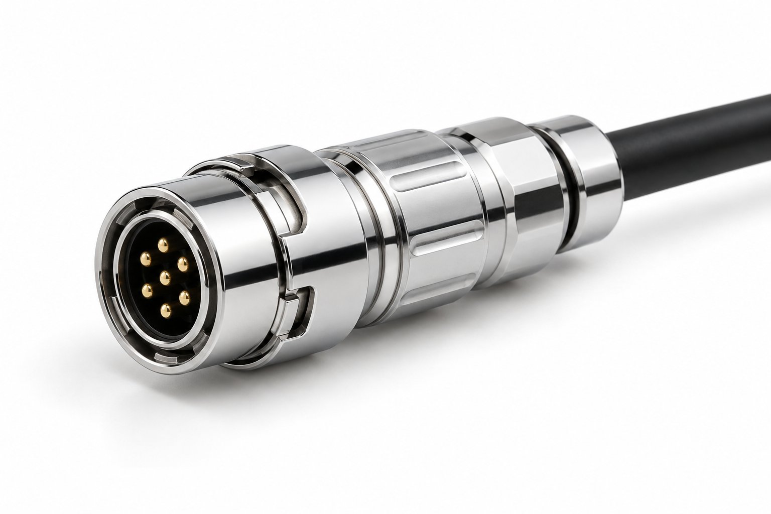
B Series TGG Push-Pull Straight Plug (product page). Terminations solder, crimp or PCB; 2–32 pins; IP50; more than 5,000 mating cycles; working temperature -55 °C to +250 °C; vibration 10–2000 Hz at 15 G; shock 100 G for 6 ms; salt spray more than 144 h; shielding more than 75 dB at 10 MHz and more than 40 dB at 1 GHz; shell sizes 0B/1B/2B; brass chrome-plated shell with PPS insulator; straight and 90° exits; multi-position keying with G-type standard key.
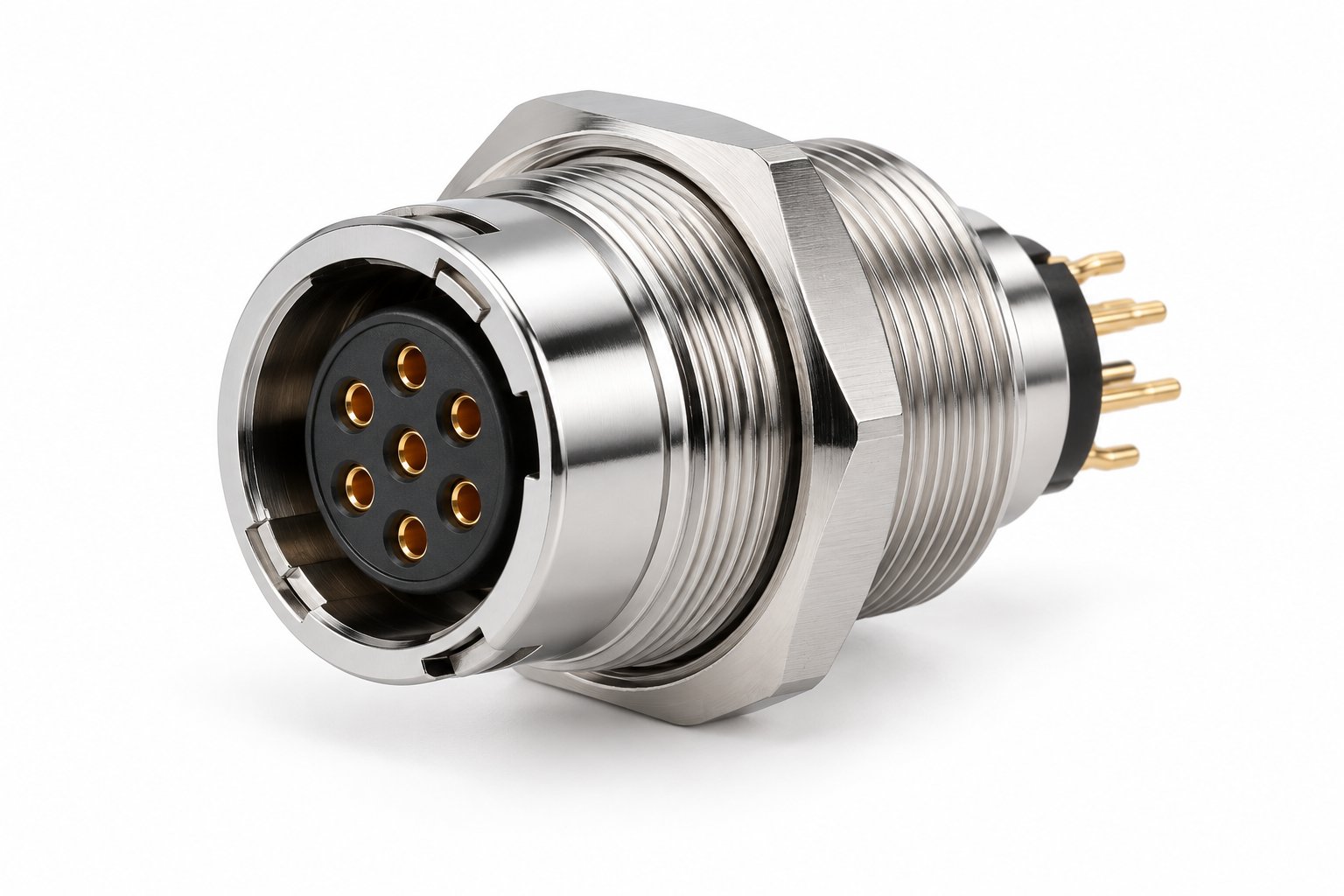
B Series ZEG Outer Fixed Socket (product page). Solder-wire and PCB layouts in the same shell; shell sizes 00B/0B/1B/2B/3B/4B; 2–32 contacts; IP50 mated; more than 5,000 mating cycles; -55 °C to +250 °C; insulation resistance ≥ 5,000 MΩ; contact resistance ≤ 10 mΩ; salt spray more than 144 h; IEC 61076-2-010 and RoHS; external mounting thread with lock washer through a plain clearance hole; keying 0° (G) standard, with A/B/C/J/F at 30/60/90/45/155° positions.
B Series ZGG Push-Pull Fixed Socket (product page). Terminations solder, crimp or PCB; 2–32 pins; IP50; more than 5,000 mating cycles; -55 °C to +250 °C; shell sizes 0B/1B/2B; internal nut fixing behind the panel.
The B Series in IP50 is the right starting point when the connector is inside an enclosure or on a panel that is not exposed to washdown or immersion. Where the mated interface has to be sealed, the F Series carries the sealed construction.
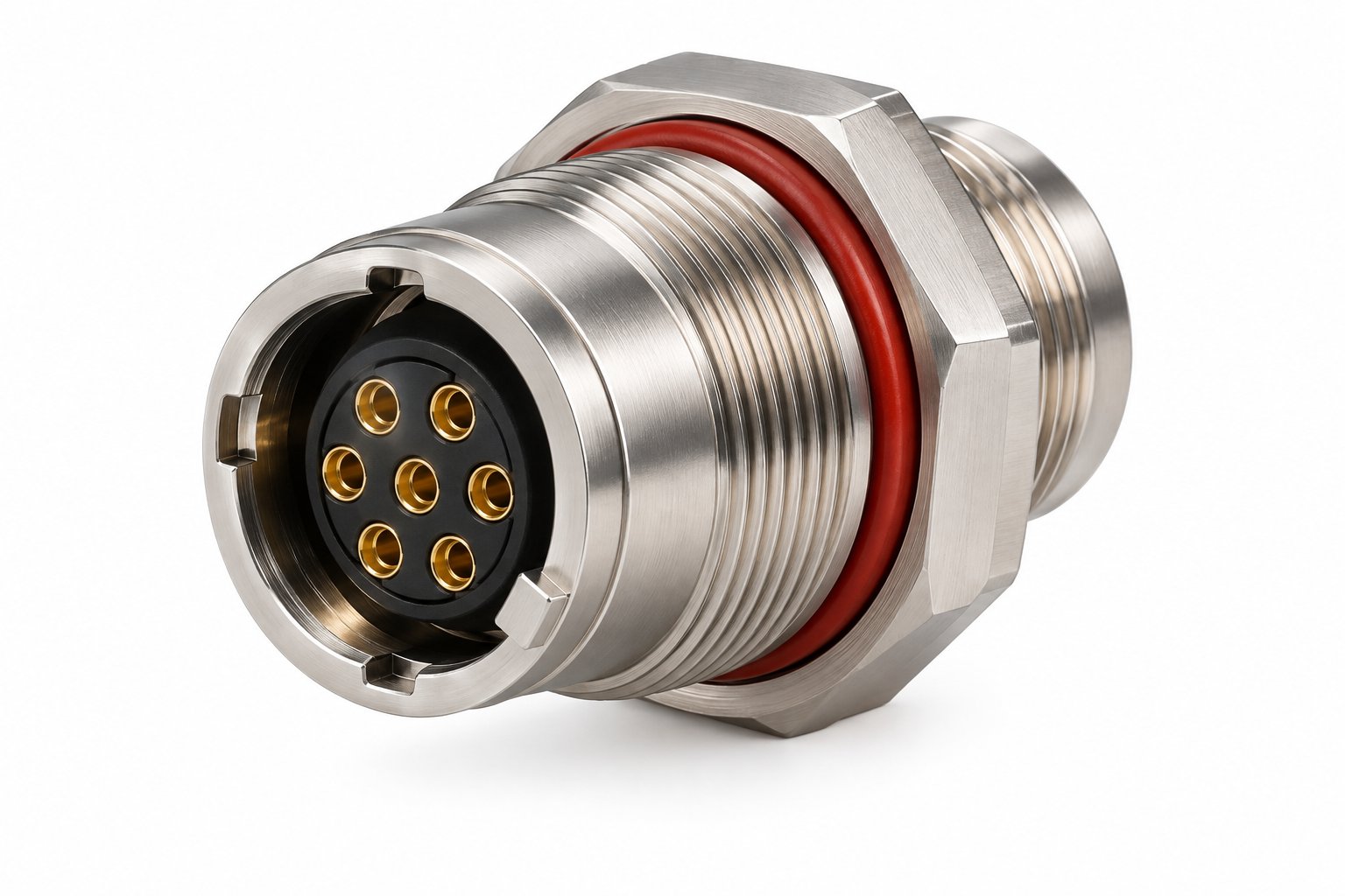
F Series ZLG Outer Sealed Fixed Socket (product page). Solder-wire and PCB layouts; shell sizes 0F (102F) and 1F (103F); 2–12 contacts; IP68 mated; more than 5,000 mating cycles; -55 °C to +250 °C; IEC 61076-2-010; external thread with front O-ring sealing against the housing wall.
Both series share the same temperature envelope of -55 °C to +250 °C, which is a wide band and one of the reasons solder cups remain practical on these connectors: the contact system does not depend on an elastomer or a plastic latch to hold the termination, so the termination is not the limiting element in the thermal path.
Buyer FAQ
Can I mix solder and PCB terminations in one order?
On the B Series ZEG outer fixed socket, solder-wire and PCB layouts are offered in the same shell, and the TGG plug and ZGG socket list solder, crimp and PCB terminations. Whether a specific pin count and shell size can be supplied in both layouts in one order is a question for the supplier at quotation stage; state the split in the inquiry.
Is solder cup suitable for a crimp-trained harness shop?
Yes, but the controls are different. There is no crimp tool to certify, so the shop needs a soldering workmanship standard, a visual inspection step before the rear shell is fitted, and a rework method. A shop that already builds solder cup assemblies can usually absorb the work with an existing bench.
How do I know the cup will accept my wire?
Give the supplier the conductor size and the insulation outside diameter per wire, plus the overall cable diameter if applicable, and ask for confirmation of the accepted ranges for the chosen shell size and pin count. Cup bore and rear insert diameter are separate constraints, and the insert is usually the tighter one.
What does IP50 mean for a solder cup connector?
IP50 is the rating published for the B Series connectors, both mated and as specified in the product data. It is not a washdown rating. If the application requires the mated interface to be sealed, the F Series ZLG socket is rated IP68 mated and uses a front O-ring against the housing wall.
Can the connector be reworked after the rear shell is fitted?
Rework after the shell is closed is impractical on most solder cup plugs because the joints are no longer accessible. The inspection step has to happen before the rear hardware goes on. On a panel socket where the cups remain exposed on the rear face, rework is physically possible but still requires desoldering, with the insulation risk that carries.
How many mating cycles will the connector take?
The B Series and F Series models listed here are published at more than 5,000 mating cycles. That figure describes the contact and locking system, not the solder joints, which are permanent and not part of the mating cycle count.
Do I need to specify keying if I only use one connector?
If there is any chance a second connector of the same shell size will be on the same panel or in the same service kit, specify a non-standard keying position. The B Series ZEG offers 0° (G) standard plus A, B, C, J and F at 30/60/90/45/155°. Keying is cheap at the specification stage and impossible to retrofit to a finished harness.
What should the inquiry include?
Pin count, termination style, shell size, conductor and insulation dimensions or cable diameter, exit direction, keying position, panel fixing type and quantity. Add the environmental requirement so the supplier can confirm whether the B Series IP50 construction or the F Series IP68 sealed construction is the right series.
Specifying a solder cup connector? Send the pin count, termination style, cable diameter, exit direction, keying position and quantity, and the TRCONN team will come back with the matching B or F Series model and the cup and insert ranges for your wire.