
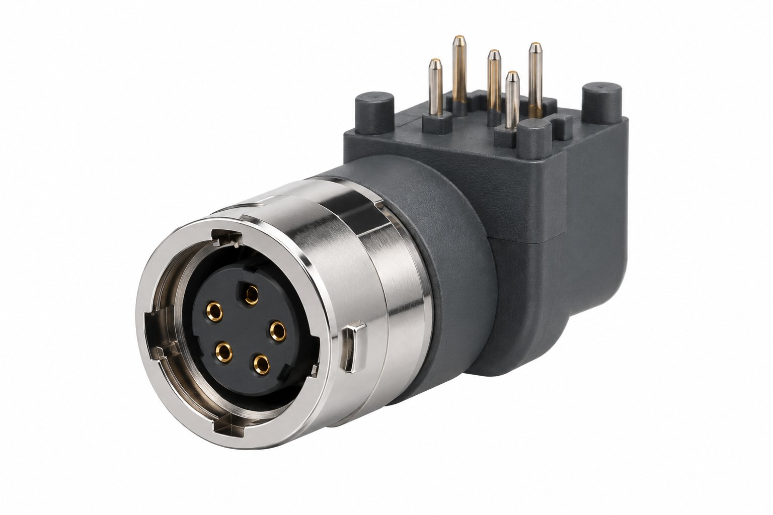
A push-pull circular connector that solders onto a PCB is not a cable connector with a different tail. The pin style decides which way the board sits relative to the panel, the fixing hardware decides whether the shell is grounded to the chassis or floating on the PCB, and the sealing class decides whether the same part number belongs inside an enclosure or through a bulkhead. This guide works through those three decisions using TRCONN's B, S, F and K Series PCB sockets.
Key takeaways
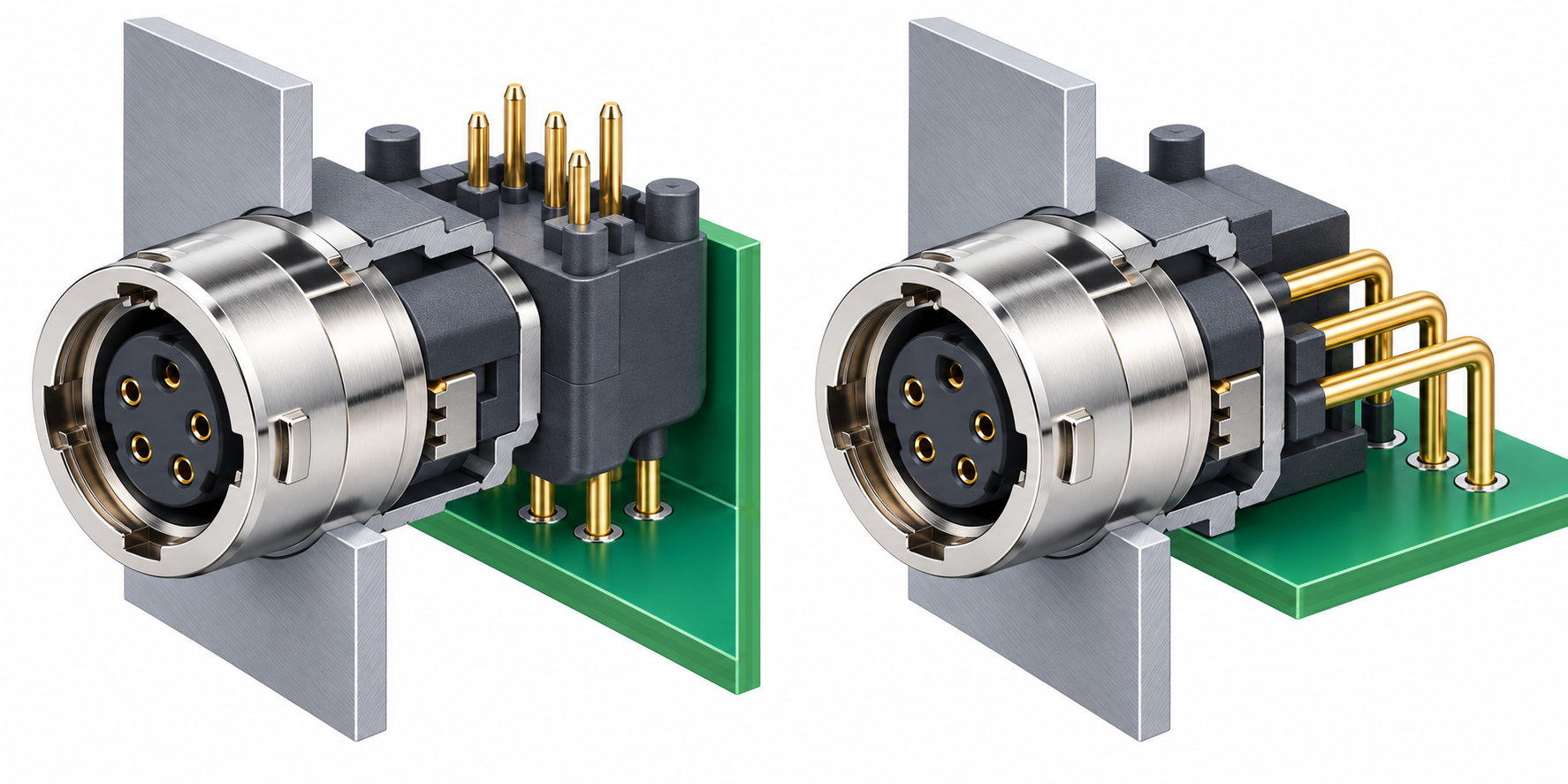
- Short straight pins suit a board mounted perpendicular to the panel face; long elbow pins suit a board parallel to the panel face.
- Pin-grid pitch is not the same across shell sizes: 5.08 mm for 00B, 7.62 mm for 0B and 1B.
- Pure board sockets, hex-nut sockets and double-nut sockets differ in how the shell is anchored and grounded.
- IP50 board sockets belong inside an enclosure; K Series and F Series sockets carry the sealing for exposed panel use.
- All families listed here are rated above 5000 mating cycles and are keyed; the keying angle must match the mating plug.
In this article
- What PCB mount means here
- Straight pins vs elbow and long elbow pins
- Panel fixing: board, hex nut, double nut
- Footprint planning with real grid dimensions
- IP50 board sockets vs sealed threaded sockets
- Environmental and electrical data
- Keying and mating
- Selection checklist
- FAQ
1. What "PCB mount" means on a push-pull connector
In a standard push-pull circular connector, the panel socket is the half that terminates wires into a solder cup. A PCB-mount socket replaces the solder cup with pins that pass through plated holes in the board and are soldered on the underside. The front of the connector is unchanged: the same shell, the same push-pull locking collar, and the same mating interface as the cable-side plug.
That distinction matters during specification because a PCB socket is bought for two things at once. It is an electrical interface, and it is a mechanical anchor for the connector shell in the panel cutout. A cable-side solder-cup socket has only one job — terminate wires — so the buyer picks a contact count and a shell size and stops there. With a PCB socket, the board drives the mechanical design. Board thickness, the position of the panel cutout relative to the board edge, whether the board is fixed to the chassis or floats on standoffs, and whether the shell needs a low-impedance path to chassis ground all become part of the connector decision.
This is also why PCB sockets are usually specified by the hardware engineer rather than the harness supplier. A wire-terminated connector can be swapped late in a project with little consequence. A PCB socket is fixed the moment the footprint is committed to copper, and changing pin style afterwards usually means a board revision.
TRCONN's PCB socket range sits across four series. The B Series covers the widest range of pin styles and fixing hardware in the 00B to 3B shell sizes. The S Series adds a hex-nut 90-degree socket in 0S and 1S with a slightly lower upper temperature band. The F Series and K Series bring sealed, threaded shells with long elbow pins for boards that sit parallel to the panel. Each format below is a genuine product family, not a variation created for this article.
One naming note before the details: in the model codes used below, "90-degree elbow" describes the socket body — the mating axis turned through 90 degrees against the board — not the shape of the solder pins. The B Series ZPG and the S Series ZXL, for example, both carry short straight pins inside that angled body. Confirm the pin format against the drawing for the exact part code rather than against the name alone.
2. Straight pins, elbow pins and long elbow pins: matching the pin to the board orientation
The single most consequential choice on a PCB socket is the direction in which the pins leave the shell. There are three formats across the range, and each one corresponds to a specific physical relationship between board and panel.
Short straight pins: board perpendicular to the panel
With short straight pins, the socket body projects straight back from the panel and the pins drop into the board at 90 degrees to the panel face. The board therefore sits behind the panel, perpendicular to it, parallel to the connector axis. This is the classic layout for a front-panel connector on a board that stands vertically inside the housing, or for a connector on the rear edge of a board behind a faceplate.
The B Series ZPG 90-degree elbow PCB socket is the reference part here: short straight pins in 00B, 0B and 1B layouts, PPS insulator, brass chrome-plated face, gold-plated contacts. It is IP50 when mated. Its angled body turns the mating axis through 90 degrees against the board while the pins stay straight.
Long elbow pins: board parallel to the panel
Long right-angle bent pins turn the board through 90 degrees so that it lies flat behind the panel, parallel to the panel face. This is the layout most often wanted when the PCB is the main internal chassis of a small instrument, or when a connector has to reach back from a front panel to a horizontally mounted board several millimetres away. The long pin length provides that standoff, so the panel face and the board surface are not required to be close together.
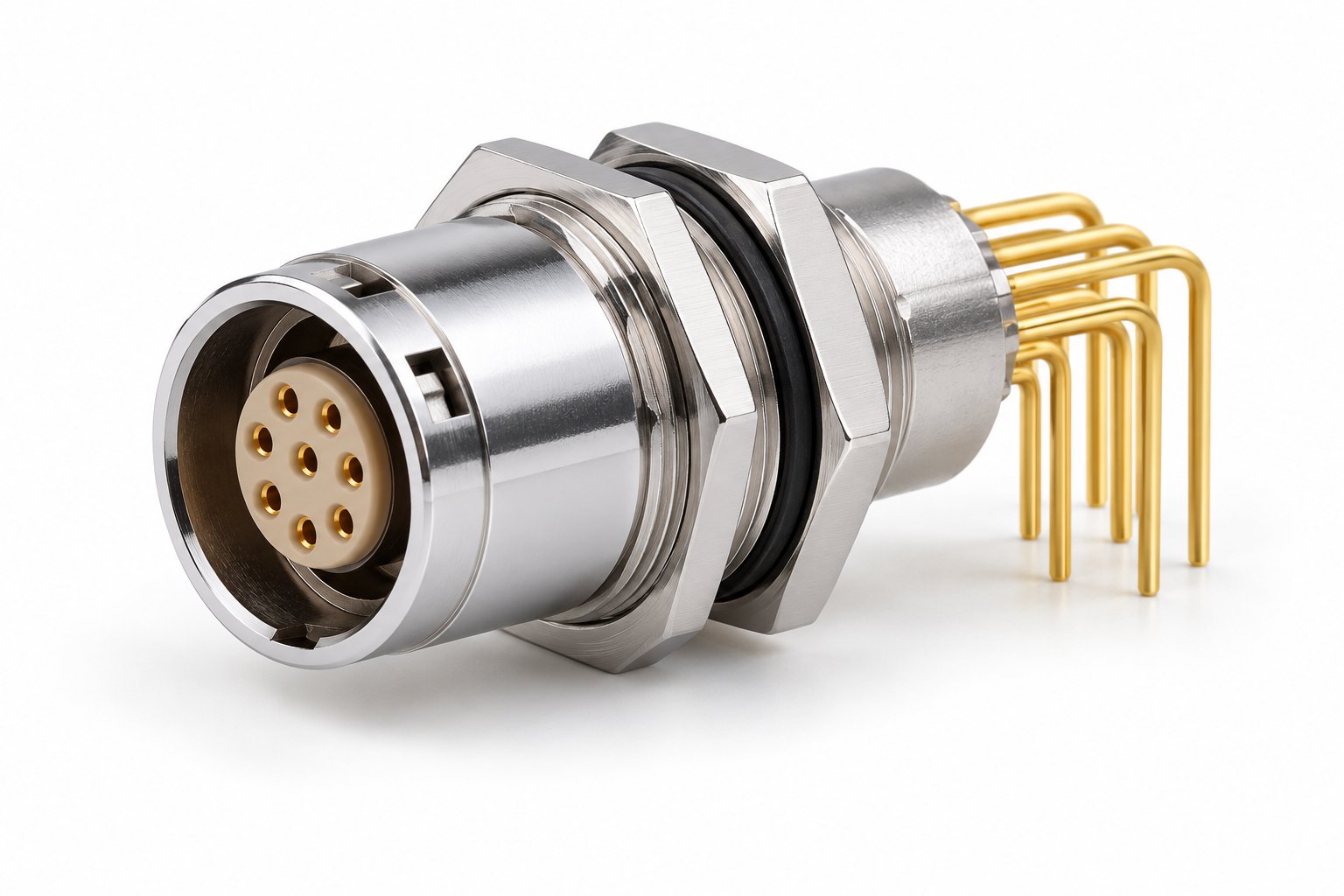
The B Series ZCG long elbow-pin PCB socket is the general-purpose version: long right-angle bent pins for boards parallel to the panel, with double-nut front fixing, in 0B, 1B, 2B and 3B layouts with 2 to 32 contacts per layout. It shares the shell, thread and mounting hardware of the standard ZCG range, which simplifies spares and panel tooling if the same cutout is used across a product family.
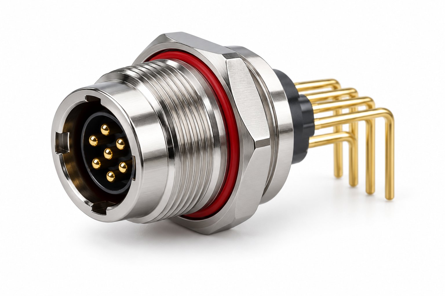
The same long elbow format carries into the sealed series. The K Series ZCG long elbow-pin PCB socket covers 0K, 1K, 2K and 3K with 2 to 30 contacts, external thread with panel sealing, brass chrome shell, PA66 insulator, and IP66-IP68 protection. The F Series ZCG long elbow-pin socket covers 0F, 1F and 1.5F (102F, 103F, 1031F) with 2 to 12 contacts, PPS insulator, IP68 mated, and mates with F Series TGG, TLG and THG plugs.
Double-nut fixing with short straight pins
The B Series ZXG double-nut 90-degree elbow PCB socket pairs double-nut panel fixing with short straight pins landing on a board perpendicular to the panel. It is the right starting point when the layout needs the mechanical grip of a double nut but the board has to stay vertical behind the faceplate. Because two fixing methods are combined in one part, confirm the exact shell size you need against the current drawing rather than assuming it mirrors a single-method family.
One further variant comes from the S Series: the S Series ZXL 90-degree elbow PCB socket with hex nut, in 0S and 1S layouts, IP50 when mated, rated -55 to +230 °C, above 5000 mating cycles, and mating with S Series TFA and TLA plugs. The lower upper temperature limit relative to the B Series is worth noting if the board sits near a heat source.
3. Panel fixing options: pure board socket, hex nut, double nut
Fixing hardware determines how the connector shell is held in the panel and, by extension, how it is connected to chassis. Three options appear across the range.
Pure board socket
Here the connector is held entirely by the pins soldered into the PCB, with no nut on the panel side. This is the arrangement with the fewest parts and the simplest assembly, and it suits designs where the board is itself rigidly fixed to the chassis and the connector does not carry any cable load beyond the push-pull retention. It is a poor choice where the connector is exposed to side load, where the panel and board can move relative to each other, or where the shell must be bonded to chassis ground independently of the PCB.
Hex nut fixing
A single hex nut clamps the shell to the panel from behind. The S Series ZXL uses this arrangement. It gives a defined clamping force, keeps the connector square in the cutout, and provides a metal-to-metal path from shell to panel where the panel is conductive — relevant for shielding continuity. A hex nut is quicker to assemble than a double nut and occupies less depth behind the panel.
Double-nut fixing
Two nuts clamp the panel between them, so the shell is anchored from both sides. The B Series ZCG and ZXG and the K and F Series ZCG all use double-nut front fixing. The advantage is mechanical: the connector does not rely on the board for positional stability, and the assembly tolerates a wider range of panel thickness without a separate spacer. It also allows the connector to be tightened or replaced from the front of the panel in some installations, which matters for field service. The cost is depth and assembly time.
| Fixing method | Where the shell is anchored | Typical use | Watch for |
|---|---|---|---|
| Pure board socket | PCB only, via soldered pins | Board rigidly fixed to chassis, light cable load, enclosed equipment | No independent shell grounding; side load goes into solder joints |
| Hex nut | Panel, single nut behind | Compact instruments, defined clamping force needed | Limited tolerance for panel thickness variation |
| Double nut | Panel, clamped both sides | Front-serviceable connectors, thicker or variable panels | Greater depth behind panel; more assembly steps |
4. Footprint planning with the real grid dimensions
The footprint is where PCB sockets most often go wrong, because pitch changes with shell size and because a bent-pin socket occupies board area in two directions. The confirmed grid figures for the B Series are:
| Shell size | Pin grid R dimension | Pin diameter |
|---|---|---|
| 00B | 5.08 mm | 0.5 mm |
| 0B | 7.62 mm | 0.7 mm |
| 1B | 7.62 mm | 0.7 mm |
The 0.5 mm pin in 00B and the 0.7 mm pin in 0B and 1B set the minimum finished hole size and the annular ring you can afford. A 0.7 mm pin is roughly 40 percent larger in diameter than a 0.5 mm pin, which changes the drill schedule and the amount of copper left between holes on a fine-pitch layout. On a dense board, it is worth deciding shell size before routing the connector region rather than after.
For the bent-pin families, the board-parallel format adds a second consideration: the pin length forms a standoff, so the board surface sits a fixed distance behind the panel face. That distance, together with the R dimension, fixes where the board can be placed relative to the cutout. Lay out the cutout, the connector footprint and the board standoff in a single side-elevation drawing. If the standoff conflicts with a component on the board, the problem appears at first assembly, not at layout review.
Two further planning points apply across the range:
- Contact count drives shell size before pitch does. The B Series ZCG spans 2 to 32 contacts across 0B to 3B, the K Series ZCG spans 2 to 30 across 0K to 3K, and the F Series ZCG spans 2 to 12 across 0F to 1.5F. Confirm the contact arrangement within the chosen shell size, since the same shell can carry different layouts.
- Consider service access. If the connector must be removed without desoldering, only a nut-fixed design allows that. A pure board socket is effectively permanent once soldered.
Where the exact hole pattern, keep-out area or recommended pad geometry for a specific layout is not on the drawing you hold, request the current footprint drawing for that part number through the contact page at the end of this article, quoting the shell size, contact layout and keying code, before releasing the board. Pad geometry and drilled hole tolerances are not values to be inferred from pin diameter alone.
5. IP50 board sockets vs sealed threaded PCB sockets
Sealing is the second major fork in the decision, and it is usually settled by one question: is the connector inside an enclosure, or is it the enclosure boundary?
When IP50 is enough
An IP50 mated rating means protection against dust ingress in a limited sense and no protection against water. The IP50 board sockets in the range — the B Series ZPG and the S Series ZXL — are designed for equipment where the connector sits behind a sealed front panel or inside a cabinet, and the panel cutout itself is not the environmental barrier. In that case the IP50 rating describes the connector interface, not the equipment enclosure. Nothing is gained by paying for a sealed shell if the panel around it is not sealed.
When to move to a sealed threaded socket
When the connector is the environmental boundary — an outdoor instrument housing, a washdown area, a field-deployed enclosure — the socket itself must carry the seal. Two families in the range do this:
- K Series ZCG long elbow-pin PCB socket: IP66-IP68, external thread with panel sealing, brass chrome shell, PA66 insulator, shielding effectiveness above 95 dB at 10 MHz and above 80 dB at 1 GHz, rated -55 to +250 °C. This is the family to look at when both ingress protection and EMC performance across a broad frequency range matter.
- F Series ZCG long elbow-pin socket: IP68 mated, PPS insulator, 0F to 1.5F, with mating F Series TGG, TLG and THG plugs.
The external thread on the K Series is part of the sealing system as well as the mounting system: the thread compresses the panel seal. That means the cutout and panel finish must suit a threaded, sealed mount — a thin, soft or painted panel may need a different approach than an unsealed nut-fixed socket would tolerate. If the panel material or thickness is unusual, raise it with the supplier before committing.
Note that IP66-IP68 covers a range rather than a single figure. The grade actually achieved depends on the mated condition and the panel installation, so if a specific IP level is a contractual requirement, state the level and the test condition in the request rather than relying on the range description.
6. Environmental and electrical data
The table below collects the confirmed figures across the PCB socket families discussed. Values that are not listed here — current rating, voltage rating, wire gauge, torque — are not published in this article and should be requested for the specific part number.
| Parameter | B Series ZPG | S Series ZXL | K Series ZCG | F Series ZCG |
|---|---|---|---|---|
| Shell sizes | 00B, 0B, 1B | 0S, 1S | 0K, 1K, 2K, 3K | 0F, 1F, 1.5F |
| Contacts per layout | 2–32 | — | 2–30 | 2–12 |
| Pin format | Short straight | Straight | Long elbow | Long elbow |
| Ingress protection (mated) | IP50 | IP50 | IP66-IP68 | IP68 |
| Temperature range | -55 to +250 °C | -55 to +230 °C | -55 to +250 °C | -55 to +250 °C |
| Mating cycles | >5000 | >5000 | >5000 | >5000 |
| Insulator | PPS | PPS | PA66 | PPS |
| Shell / face | Brass, chrome-plated face | Brass, chrome-plated face | Brass, chrome | Brass, chrome-plated |
| Contacts | Gold-plated | Gold-plated | Gold-plated | Gold-plated |
| Insulation resistance | ≥5000 MΩ | — | — | — |
| Contact resistance | ≤10 mΩ | — | — | — |
| Vibration | 10–2000 Hz, 15 G | — | — | — |
| Shock | 100 G, 6 ms | — | — | — |
| Shielding | — | — | >95 dB at 10 MHz; >80 dB at 1 GHz | — |
| Standard | IEC 61076-2-010 | — | IEC 61076-2-010 | IEC 61076-2-010 |
| RoHS | Yes | — | — | — |
A dash means the value was not part of the confirmed data set for this article, not that the product lacks the property. Where a parameter is missing and matters to your design — contact resistance for the K Series, for example — ask for the datasheet for the exact part number, quoting the shell size, contact layout, board orientation and sealing class.
The B Series ZPG figures are the most complete in the range, and they are a useful reference point for what the wider family is engineered to withstand: vibration testing to 15 G across 10 to 2000 Hz and a 100 G, 6 ms shock test. If your application is in a vehicle, a machine tool or anything that vibrates, quote the requirement in the enquiry so the supplier can confirm the applicable test data for the part you intend to use rather than relying on another family's figures.
7. Keying and mating
All the PCB sockets in this range are keyed, so a plug can only be inserted in one angular position. The B Series uses a positioning-pin keying system with 0 degrees (G) as standard and catalogue options at 30, 60, 90, 45 and 155 degrees (A, B, C, J, F). If a panel carries two or more connectors of the same shell size, different keying codes prevent cross-mating — a common requirement in multi-channel instruments and a cheap way to remove a whole class of assembly error.
Keying must be specified at the same time as the socket, because the mating plug has to match. A keying code on the socket without the corresponding plug code creates a pair that will not mate, and the error usually surfaces at the harness build stage rather than at layout. Record the keying angle on both the socket and plug drawings.
The plug series also confirm which cable-side part each socket family is designed to meet. The S Series ZXL mates with S Series TFA and TLA plugs; the F Series ZCG mates with F Series TGG, TLG and THG plugs. Ensuring the socket and plug come from the same series and the same keying code is the minimum check before any order.
Mating cycles are above 5000 across all the families covered here. That figure describes the connector interface; it does not describe how often the soldered pins can be reworked. If your service model requires repeated board removal, plan for that mechanically rather than assuming the connector rating covers it.
8. Selection checklist
Work through the following in order. Each step narrows the range before the next one is applied.
- Confirm the series by sealing requirement. Inside an enclosure with a sealed front panel: B Series or S Series with IP50. The connector is the environmental boundary: K Series (IP66-IP68) or F Series (IP68).
- Fix the board orientation. Board perpendicular to the panel: short straight pins (ZPG, ZXG). Board parallel to the panel: long elbow pins (B, K and F Series ZCG).
- Choose the fixing method. Pure board socket where the board is rigid and the shell needs no independent ground. Hex nut for compact, defined clamping. Double nut where the connector is front-serviceable or the panel varies.
- Count contacts and pick shell size. Check the layout within the shell size — 2 to 32 contacts in B Series ZCG, 2 to 30 in K Series ZCG, 2 to 12 in F Series ZCG.
- Lay out the footprint. Apply the R dimension and pin diameter for the shell size: 5.08 mm and 0.5 mm for 00B; 7.62 mm and 0.7 mm for 0B and 1B. Request the current footprint drawing for the exact part number.
- Confirm the environment. Temperature range, vibration and shock requirement for the specific family; ask for test data where the requirement is contractual.
- Set the keying code. Standard 0 degrees (G) or the 30, 60, 90, 45 and 155 degree catalogue options on B Series, and match the plug.
- Check grounding. If the shell must bond to chassis, use a nut-fixed installation on a conductive panel and confirm the path with the supplier.
9. FAQ
Can I use a cable solder-cup socket on a PCB instead?
No — the two are different termination formats. A solder-cup socket terminates wires; a PCB socket terminates into plated through-holes. The mounting is different too, and a solder-cup socket has no pin grid to lay out against. If you need a wire connection at the board, that is a harness termination on the plug side, not a substitute for a PCB socket.
Why is the pin pitch different between 00B and 0B/1B?
The 00B shell uses a 5.08 mm pin grid with 0.5 mm pins, while 0B and 1B use a 7.62 mm grid with 0.7 mm pins. The larger shell accommodates more contacts and larger pins, so the footprint has to be laid out per shell size rather than with one generic pattern.
Does the IP rating of the socket tell me the enclosure rating?
No. An IP50 mated socket is not a water barrier, and if it sits behind an unsealed panel the equipment is not protected by it. Conversely, an IP66-IP68 or IP68 socket is only sealed as installed, which depends on the panel seal, cutout and mounting. The achievable level in service depends on the full assembly and should be stated in the requirement.
What if I need a current or voltage rating that is not listed?
Request it for the specific part number. Ratings are not created by extrapolation from the contact diameter or from another family's datasheet — they are confirmed against the part you intend to buy.
Can the connector be reworked if the board has to be replaced?
Mechanically, a nut-fixed socket can be released from the panel, but the pins are soldered to the board, so the connector itself still comes out with the board unless it is desoldered. Plan service access around board removal rather than around removing the connector alone.
Tell us your board and panel geometry
To match a PCB socket to your design, we need the board orientation, the panel cutout or shell size you have in mind, the contact count, and the sealing class your enclosure demands. Send the side-elevation drawing if you have one — it settles the pin-style question fastest.