
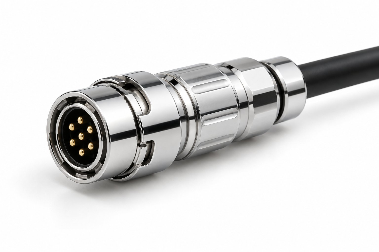
Choosing a circular push pull connector comes down to four decisions: shell size and pin count, IP rating, keying, and termination. Get those four right and the rest of the specification — cable exit, mounting style, mating cycles — follows from the application. This walkthrough takes you through each decision in the order a design engineer or buyer actually makes it, and ends with a specification checklist you can hand to a supplier.
Key takeaways
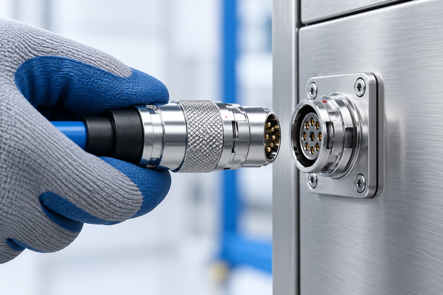
- The push-pull locking mechanism mates and releases by sliding the outer sleeve — no rotation, no tools, one hand.
- Shell size and pin count set the contact layout; choose the smallest shell that carries the required pins and cable bundle.
- IP50 suits protected indoor cabinets; IP68 is for wash-down, outdoor and wet environments.
- Keying prevents mismating between adjacent connectors of the same shell size — specify the code that matches your panel layout.
- Termination (solder, crimp, PCB) and mounting style (plug, panel socket) must match your assembly process, not the other way round.
In this article
- What a circular push-pull connector is
- When push-pull beats threaded or bayonet latching
- Factor 1: shell size and pin count
- Factor 2: IP rating and environment
- Factor 3: keying and mis-mating prevention
- Factor 4: termination and mounting
- Application mapping
- B2B purchasing FAQ
- Specification checklist and inquiry checklist
- Specify your connector
What a circular push-pull connector is and how the locking mechanism works
A circular push pull connector is a multi-pin circular connector that mates by pushing the plug onto the socket and unmates by pulling back the outer sleeve. There is no threaded coupling ring to turn and no bayonet pins to align. The mechanism is a spring-loaded latch inside the plug shell: when you push the plug home, the latch engages on the socket shell and gives a tactile click and a small axial travel that tells the operator the connection is seated. To release, you slide the sleeve rearward; the sleeve lifts the latch and the plug withdraws. Pulling on the cable or the rear of the plug does not release the latch — only the sleeve movement does. That distinction is the safety property that makes push-pull connectors common on machines where a cable snag must not disconnect a running circuit.
In practice this means one-hand, no-tools mating. An operator can connect a sensor or a camera cable in a panel without a wrench, and can do it blind when the connector is behind a guard or inside a cabinet. The audible and tactile confirmation matters on a production line: the operator does not have to look at the connector to know it is locked.
TRCONN manufactures push-pull circular connectors across the B, S, F, K, T, W, P, HR and RJ45 series. The B and F series are the core of the range for general industrial and sealed applications; HR10 serves machine vision and automation signal lines; RJ45 covers industrial Ethernet. The selection factors below apply across the range, with series-specific differences noted where they matter.
When push-pull beats threaded or bayonet latching connectors
The three latching styles solve different problems, and the right choice depends on how often the connector is mated and who does it.
Push-pull
Fast, one-hand mating and release. No tools. Tactile confirmation. Good for frequently mated points, blind mating, and connectors on moving or frequently serviced equipment. The sleeve is the only release path, which resists accidental disconnection from cable pull.
Threaded
High retention and vibration resistance, but slower to mate and requires access for fingers or a tool. Suited to connections that are made once and left for the life of the machine, or where a locking thread is required by the installation standard.
Bayonet
Quarter-turn lock with a positive click. Faster than threaded, but still needs rotational access and two hands in tight spaces. Common in legacy audio and instrumentation designs.
When to stay with push-pull
If the connector will be mated repeatedly in service, sits behind a panel, or is handled by production staff rather than technicians, push-pull is usually the practical choice. Confirm the retention and sealing requirements with the supplier before switching an existing threaded design.
The current-carrying and voltage ratings of a given connector depend on the contact size and the number of energized contacts, so they are set by the specific variant. Ask the supplier for the rating of the exact pin count and termination you intend to use rather than assuming a family-level figure.
Selection factor 1: shell size and pin count
Shell size determines the contact layout, the cable entry, and the panel footprint. The rule is to choose the smallest shell that carries the required number of contacts and accepts the cable bundle, then check that the resulting connector fits the available panel space.
Shell sizes are designated by a number and a letter — 0B, 1B, 2B, and so on. Within a series, a larger shell number carries more contacts and a larger cable. Pin count ranges overlap between shells, so a given pin count may be available in more than one shell; the smaller shell is denser, the larger shell gives more room for termination and cable bending.
| Series / product | Pin count | Shell sizes | Notes |
|---|---|---|---|
| B Series TGG straight plug | 2–32 | 0B / 1B / 2B | Brass chrome-plated shell, PPS insulator, solder/crimp/PCB termination, straight and 90° elbow exits |
| B Series ZEG outer fixed socket | 2–32 | 00B–4B | External mounting thread with lock washer, mounts through a plain hole; solder-wire and PCB layouts |
| F Series TGG high-sealing plug | 2–27 | — | IP68, ring-shaped guiding groove aligns halves before contacts engage |
| HR10 machine vision plug | 4 / 6 / 8 / 10 / 12 | — | IP50, push-pull or threaded (T version) locking, pin/socket contacts |
Count the pins you actually need, including spare positions for future signals, then confirm the shell size against the cable outside diameter. A connector that is electrically correct but forces a tight bend radius at the backshell will fail in service. If the cable is thick and the pin count is high, a larger shell with a 90° elbow exit is often the better mechanical fit than a dense straight plug.
Selection factor 2: IP rating and environment
IP rating is the second decision because it eliminates whole product families. The two ratings that dominate industrial connector selection are IP50 and IP68, and they answer different questions.
IP50 — dust-protected, not water-rated
IP50 means the enclosure is protected against dust ingress in normal operation but is not rated for water. IP50 connectors suit cabinets, control boxes, and indoor machine wiring where the connector is not exposed to splashing or wash-down. The B Series TGG plug and the HR10 machine vision plug are IP50. For the B Series, the IP50 rating is specified for the mated plug-and-socket pair, so confirm the rating of your exact plug–socket combination with the supplier. A common specification error is to use an IP50 connector on a machine that gets hosed down at the end of a shift; the connector will pass a bench test and fail in the field. If the environment includes wash-down, coolant spray, or outdoor exposure, move to an IP68 family.
IP68 — wash-down and outdoor
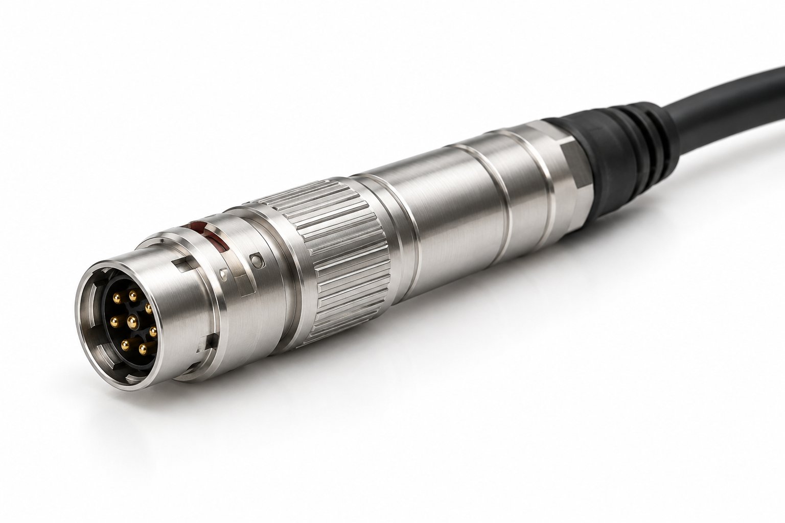
IP68 is the rating to specify for a waterproof circular connector that faces direct water, outdoor weather, or hygienic wash-down. The F Series TGG high-sealing long straight plug is IP68 and uses a ring-shaped guiding groove that aligns the two halves before the contacts engage, which protects the contacts during blind mating in wet conditions. For equipment that is cleaned regularly or installed outdoors, IP68 is the baseline, not an upgrade.
Sealing is a system property: the rating applies to the mated pair, and the cable entry must be sealed to the same level. When you request a quote, state the mated IP rating and the cable diameter so the supplier can confirm the correct gland and backshell. Do not assume an IP68 plug stays IP68 with an oversized cable jacket or an unterminated rear.
Also check the temperature range against the environment. The B Series TGG plug and the F Series TGG plug are rated from -55°C to +250°C; the HR10 machine vision plug is rated -20°C to +80°C. Other variants in each series carry their own ratings, so confirm the figure for the exact part you specify.
Selection factor 3: keying and mis-mating prevention
Keying is the factor most often left to the last minute, and keying errors are costly and hard to detect once a machine is commissioned. When two connectors of the same shell size are mounted next to each other — two sensor lines, two motor phases, two camera links — an operator can plug the wrong cable into the wrong socket. The connectors mate physically, so nothing stops the error except the keying.
Keying is a positioning-pin arrangement that allows the plug to seat in only one rotational orientation. The B Series offers positioning-pin keying at 0° (code G, the standard), 30° (A), 60° (B), 90° (C), 45° (J), and 155° (F) positions. By assigning a different key position to each adjacent connector, you make cross-mating mechanically impossible rather than relying on labels or cable colors.
The selection principle is to map the keying at the panel design stage, not at the cable assembly stage. List every same-size connector on the panel, assign a distinct key code to each circuit, and keep the assignment with the drawing. When ordering replacement cables, the key code is part of the part number — a cable built to the wrong code will not mate, which is the intended result. Confirm the available key positions for your specific shell size and series with the supplier, because the code set depends on the contact layout.
Selection factor 4: termination and mounting
Termination and mounting decide whether the connector fits your assembly process. The electrical selection is already done by this point; this step is about how the part is built into the harness and the panel.
Termination: solder, crimp, or PCB
- Solder — a permanent, low-tooling joint suited to low and medium volume and to field repair with a soldering iron. The B Series TGG plug offers solder termination.
- Crimp — a repeatable, inspectable joint that suits volume harness production and allows contact replacement. Also available on the B Series TGG plug.
- PCB — the connector mounts directly to a board, removing the wire-to-board harness. The B Series TGG plug and the HR10 plug offer PCB termination, and the B Series ZEG socket is available in PCB layouts.
Choose the termination that matches the harness shop's process and the volume. A crimp connector specified into a solder-only assembly line adds tooling and training; a solder connector specified into an automated harness line adds labor. Neither is wrong, but the mismatch is a cost that shows up after the first production run.
Mounting: plug, panel socket, and the panel hole
The plug terminates the cable; the socket mounts to the panel or chassis. The B Series ZEG outer fixed socket uses an external mounting thread with a lock washer and mounts through a plain hole — no threaded panel cut is required. That suits thin panels and plastic housings where cutting a thread is impractical. The socket is available in shell sizes 00B to 4B with 2–32 contacts, insulation resistance ≥5,000 MΩ, contact resistance ≤10 mΩ, and full-metal shielding of ≥75 dB at 10 MHz and ≥40 dB at 1 GHz. It is built to standard IEC 61076-2-010 and is RoHS compliant.
For shielded circuits — machine vision, measurement, industrial Ethernet — the shield termination is part of the selection. Confirm how the cable shield bonds to the connector shell and whether the panel socket maintains the shield through the bulkhead.
Application mapping
The four factors resolve into recognizable patterns by application. Use this mapping to shortlist a family, then confirm the exact variant with the supplier.
| Application | Typical family / product | Selection notes |
|---|---|---|
| Industrial equipment and medical devices | B Series TGG plug, B Series ZEG socket | IP50 in protected enclosures; 2–32 pins; solder, crimp, or PCB termination; >5,000 mating cycles |
| Outdoor devices and wash-down equipment | F Series TGG high-sealing plug | IP68; 2–27 pins; ring-shaped guiding groove for blind mating; long/short straight and 90° elbow exits |
| Machine vision, cameras, robots, drones | HR10 straight plug | IP50; 4/6/8/10/12 pins; push-pull or threaded (T version) locking; solder/PCB termination |
| Industrial Ethernet on machines and moving axes | RJ45 industrial molded connector | Straight, elbow, or flat head styles; vertical or horizontal locking; molded or field-terminable versions |
The B and F series share the push-pull locking mechanism and the same vibration and shock ratings — 10–2000 Hz at 15 G and 100 G at 6 ms — and both exceed 5,000 mating cycles. The difference is sealing: B for protected environments, F for wet ones. The HR10 is a smaller-format connector for signal lines where a miniature circular connector is required and the environment is dry.
B2B purchasing FAQ
What is the difference between IP50 and IP68 for a circular connector?
IP50 is dust-protected but not water-rated; it suits cabinets and indoor machine wiring. IP68 is sealed against water ingress and is the rating to specify for wash-down, outdoor, or wet environments. The rating applies to the mated pair, so the cable entry must be sealed to the same level.
Can I use a push-pull connector where a threaded connector was specified?
Often yes, but check two things first: the panel cutout and mounting thread of the existing socket, and the retention requirement of the installation. Push-pull gives fast, tool-free mating with a sleeve-release latch; if the installation standard requires a threaded lock, keep the threaded version or confirm the alternative with the supplier.
How many mating cycles can I expect?
The B Series TGG plug and the F Series TGG high-sealing plug are rated for more than 5,000 mating cycles. The HR10 is specified for machine vision and signal-line use; confirm its cycle rating for your application with the supplier.
Do I need to specify keying?
Yes, whenever two or more same-size connectors are mounted near each other. The B Series offers positioning-pin keying at 0° (G), 30° (A), 60° (B), 90° (C), 45° (J), and 155° (F). Assign a distinct code per circuit at the panel design stage.
What termination should I choose?
Solder for low-to-medium volume and field repair; crimp for repeatable harness production with replaceable contacts; PCB for board-mounted connections. The B Series TGG plug and the HR10 plug offer PCB termination, and the B Series ZEG socket is available in solder-wire and PCB layouts.
Can the connector be mounted through a plain panel hole?
The B Series ZEG outer fixed socket mounts through a plain hole using an external mounting thread and lock washer, which suits thin panels and plastic housings. Other mounting styles may require a threaded cut; confirm the panel preparation with the supplier before drilling.
Specification checklist and inquiry checklist
When you are ready to request a quote, the supplier needs enough information to select the exact variant. Use the specification checklist to confirm your design is complete, then use the inquiry checklist as the message you send.
Specification checklist
- Pin count, including spare positions for future signals
- Termination type: solder, crimp, or PCB
- Shell size and series (B, F, HR, or other)
- Keying code, if adjacent same-size connectors exist
- Sealing environment: IP50 protected or IP68 wet/outdoor
- Cable outside diameter and required bend radius
- Mounting style: cable plug, panel socket, or PCB mount
- Cable exit: straight or 90° elbow
- Temperature range of the installation
- Shielding requirement, if the circuit is shielded
Inquiry checklist — what to state in your message
- Pin count — the number of contacts required.
- Termination — solder, crimp, or PCB.
- Shell size — or the panel space available if the size is not yet fixed.
- Keying — the code, or the number of same-size connectors on the panel.
- Sealing environment — IP50 or IP68, and whether wash-down or outdoor exposure applies.
- Cable diameter — the jacket OD at the connector entry.
- Quantity — prototype, pilot, and production volumes if known.
Adding the mounting style and cable exit to this list is usually enough for the supplier to propose a specific part number, confirm the lead time and MOQ, and verify the current and voltage ratings of the exact pin count and termination, since these depend on the contact arrangement.
Specify your connector
Send your specification to TRCONN
TRCONN manufactures push-pull self-locking circular connectors across the B, S, F, K, T, W, P, HR and RJ45 series. To get a part recommendation, send your pin count, termination type, shell size or panel space, keying code, sealing environment, cable diameter, and quantity.
Contact TRCONN