
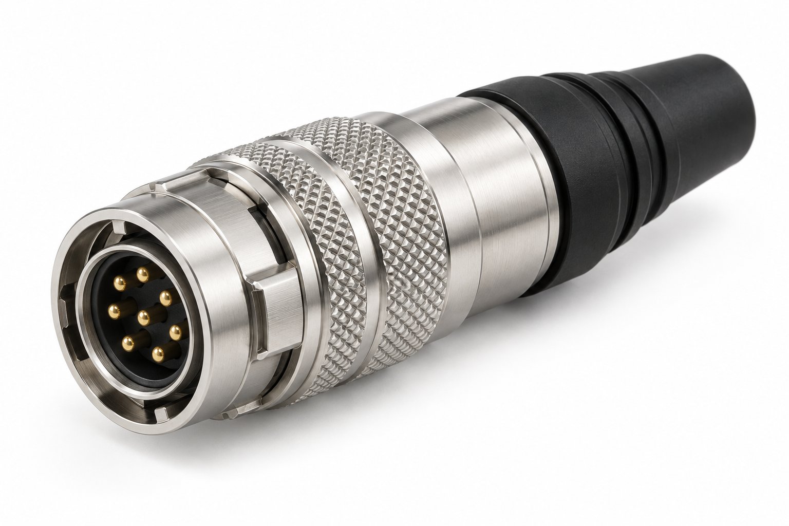
Shell size is not a styling choice on a push-pull connector — it is the output of four upstream decisions: environment, circuit count, per-circuit current and cable cross-section. Work them in order and the size picks itself; skip one and the connector usually comes back as a rework. Here is the sequence the TRCONN catalogue is built around.
Step 1: Fix the environment and series
Indoor panel or outdoor wash-down decides the series before anything else: IP50 general-purpose lines (B, F, P, S), waterproof IP66–IP68 lines (K, T) or the IP68 underwater W Series. A mismatch here cannot be patched later with seals or sleeves.
Step 2: Count circuits and load per circuit
For each circuit in the machine, note the rated voltage and the per-way current. Power, signal and coaxial ways can share one connector — several TRCONN layouts mix power and coaxial contacts in one insulator — but each way is checked against its own load. Add the circuits up to the total contact count; contact layouts run from 2 up to 32 ways depending on the series.
Step 3: Match the cable
Work out each conductor's cross-section (wire gauge / AWG) from its current, then the cable's total OD with jacket. The connector's contact bore must fit the conductor, and the tail's cable clamp must grip the jacket: D-type clamps step 3.2 / 4.2 / 5.2 / 6.2 / 7.2 mm, and finished assemblies cover 2.5–8.2 mm cable OD. Solder, crimp and PCB terminations each accept different conductor sizes, so fix the termination style before finalising the wire spec.
Step 4: Read the shell size from the contact layout
The combined pin count and layout map onto a size group — 00B/0B/1B/2B/3B/4B in the B Series, for example. A three-digit field in the part code records the count: 302 = 2 contacts, 305 = 5, 316 = 16. Confirm the chosen size gives enough panel space around each unit for the release sleeve, then verify the drilling dimensions from the catalogue table or the dimension drawing on the product page.
Worked example
A six-way signal harness with 6.2 mm OD cable on an indoor instrument: environment says B Series; six circuits say a 306 layout; the cable says a D62 clamp. The plug code lands at TGG.1B.306.CLAD62 and the panel socket at ZGG.1B.306.CLL — both readable directly from the code fields, with dimensions on the TGG sleeve version and ZGG fixed socket pages.
Where selection usually goes wrong
- Choosing the shell from the panel drawing first, then discovering the cable does not pass the clamp.
- Mixing power and signal ways without checking each way's rating.
- Forgetting rear clearance for the release sleeve — especially behind elbows, where the cable exits sideways.
Send us the circuit list with per-way loads and the cable spec, and we will return the shell size, contact layout and full part codes with drawings.
Run the selection with us