
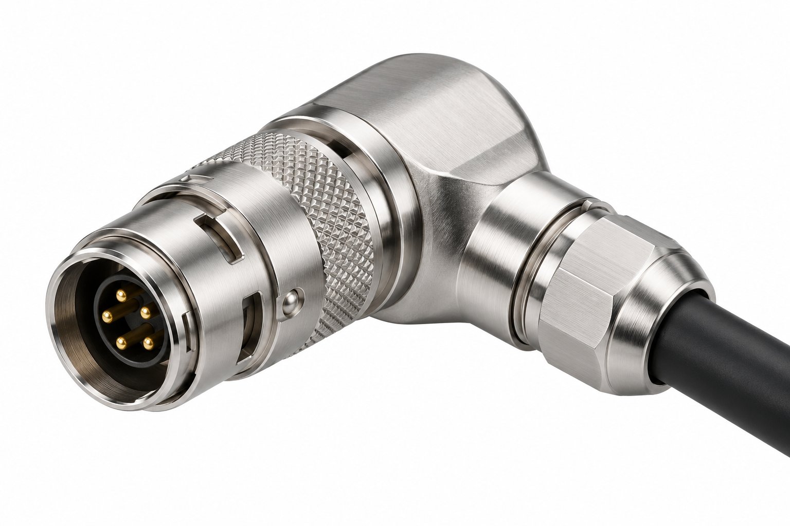
You mount several same-size connectors on one panel. Now the risk is not electrical. It is procedural. A technician in a hurry mates power line to sensor socket. Or sensor line to power socket. Keying stops this physically. The plug only enters the socket with matching key position.
Positioning-pin keying (B, K, T and W Series)
The metal push-pull series uses a key on a positioning pin. The pin is machined into the insulator. Standard position is 0°, code G. The catalogue lists 5 further pin angles. Each angle has its own code letter:
| Key angle | Code |
|---|---|
| 0° | G (standard) |
| 30° | A |
| 45° | J |
| 60° | B |
| 90° | C |
| 155° | F |
Two connectors of same shell size will not fully mate if key letters differ. The key letter is part of the part code. Example TGG versus TAG in third position. So keying is fixed at ordering. It cannot be retrofitted. This also raises contact-layout density safely. The pin layout stops contact-pair offset. The key angle stops cross-connection between similar connectors.
Half-moon keying (F Series)
The compact F Series keys use metal half-moon keying pieces inside plug and socket. 3 metal key specifications selectable. This keeps shell short. Useful where F Series compact length is the whole point. Still tells one line from another.
Stepped-insulator keying (S Series)
The S Series uses a stepped insulator profile. Plug and socket insulator contours interlock. So multi-core layouts from 00S to 4S cannot mate across different profiles. Keying lives in moulded geometry. No separate pin.
Planning keying on a real panel
- Group connectors by function. Give each group a distinct key position. Do not leave all on default 0° G.
- Keep same key scheme for spare and replacement units. Record the letter with the part code in equipment documentation.
- For elbows, the key angle also sets cable exit rotation. It sets orientation relative to the socket. Check the direction harness must leave.
- Order plugs and sockets as keyed pairs. Same drawing revision.
Keying costs nothing extra to specify. It removes a whole class of field errors. Not sure how many key positions your panel needs? Sketch the panel layout. We will propose the allocation.
Send us panel layout and connector list. We assign key positions. We return the keyed part codes.
Plan the keying